The Frac Rack system is both a compact format for use with musical electronics, and an easy format in which to DIY your own circuits. But nearly all the Frac Rack manufacturers out there are not using the full extent of either panel space or circuitry locations in the housings. I have seen a few DIY sites where someone has mounted a VCA or noise source in the end panels. And Paia offered power supplies to be mounted in the left end space. But, here are a number of simple projects which are all based on the same panel layouts, and can be mixed and matched amongst your Frac frames.
Photos of construction techniques and final implemetations are shown in the accompanying photo layout here. You may even want to open that link in a new window, so you can refer to it while reading below.
I highly recommend the use of Blacet Frac Racks when building these mods. Their panels are thinner and easier to rework, and their powder coated finish holds up well while being reworked, so the resulting panel looks just like a manufactured panel. If you have Paia racks already, these mods CAN be done, but you will need to countersink the back of the jack holes to allow the jacks to recess into the panel slightly. A little more work. But it is possible.
Construction starts with the removal of most of the front subpanel of the chassis endpieces, as shown in the first four photos. Scribe the vertical line between the two outer mounting screw locations as shown in Fig. 1. Then scribe the horizontal lines at about 3/4" from the top and bottom edges. Use your chassis nibbler to slot along the top and bottom lines, as shown in Fig. 2 and 3. Then either use the nibbler, or a very fine toothed jigsaw to cut the vertical line as shown in Fig. 4. Repeat for both chassis end panels, if you are modding both ends of the chassis.
The next step is to prep the front panels. Using the same template layout, you can either make hardwired mults, cascading mults, bias mults, and/or format conversion mults. The same layout, and pilot holes, can be used for all these. Hole sizes are fine-tuned during the final drill-out.
The basic panel layout I have settled on is
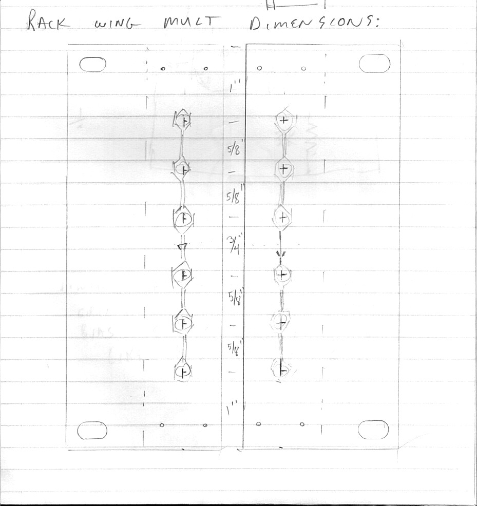
The most basic form of project is to make a simple 1X6 hardwired jack multiple, with all jacks commoned. This would give you a 1-to-5 fanout for a signal. This sized mult would be most useful for larger systems.
I usually build 2X3 1/8" Cascading Mults, as shown in Figs. 5 and 6. With the normalized connection in the middle, you can still get a 1-to-4 fanout, or 2 splitters. By substituting 1/4" jacks for the two outer positions, you can do general 1/8" to 1/4" multing, or get two 1/8"-to-1/4" format converters ... great to have in the right ear of a 9700S to get 1/4" outputs from the 9710's stereo VCA outputs!
Another great use for ear space is to provide some simple DC bias supplies. I love having bias sources sprinkled all over the system. It makes it easy to open up VCFs and VCAs while doing patch setup. By substituting a small pot in the upper position, you can create Bias-Mults that can provide voltage to up to 4 inputs, or else break away the lower splitter mult and still get 2 bias voltage outputs. This has become a favorite configuration for me, and I have several of these (Fig. 9) ... some with a 1/4" jack substituted in the lowest jack position, so I can use the bias supplies for 1/4" format modules too (Fig. 12).
A typical implementation in a finished frame is shown in Fig. 13.
(more to be added)