Custom Wiring for Use of Miata '91 OEM
Head Unit with Sony CDX1000RF
Mark Foster
March 2004; minor update: Oct 2009
Here is a summary of the wiring cable I designed and built for my '91
Miata OEM HU and Sony CDX1000RF installation. I elected to use a
relay to switch in/out the line level output from the CD Player, rather
than use the RF signal insertion. I wanted the better sonic
quality, and, more importantly (to me), closer behavior to the original
configuration. I also didn't want to have to worry about
congestion on the handful of FM channels the Sony CD player supports.
This design is derived from
a similar one
previously detailed on miata.net.
The main difference is the use of a relay, instead of a manual switch,
and use of the HU's power to operate the CD player, instead of splicing
into the OEM wiring harness. My solution is completely reversible
(no damage/change to original wiring), and works with the
original unmodified HU.
As originally designed, the OEM HU accommodates an external OEM CD
player by sending the audio signal out (pins 1, 3). If the CD
player is operating, it gates it's own signal back to the HU (pins 2,
4); if the CD player is off, then the audio from the HU is gated back
to the HU audio in. If there is no CD player installed, there is
a jumper between pins 1 and 2 and between pins 3 and 4. The relay
allows a similar functionality to the original design: when the Sony CD
player is operating, an "amp control" signal from the CD player
is used to energize the
relay's coil. This disconnects the audio from the HU and connects
the audio from the RCA line out of the Sony CD player.
One enhancement to this design was encouraged by Kevin Hennelly.
He
wanted to also control his antenna motor, so the antenna is down when
the CD is playing. This can be accomplished with a 3PDT or 4PDT,
instead of the DPDT I used.
Since I have a '91 (and no power antenna), I didn't have need for
this. But, as you can see, it's a pretty trivial change to the
overall
design.
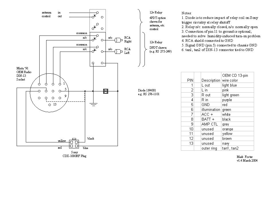
The schematic was developed from information gleaned on miata.net and
the '91 MX-5 shop manual. Although all the documentation says
pins 10-13 are "unused", they are most certainly connected inside the
HU, since grounding pin 11 addresses the humidity-induced turn-on
problem. I left them unconnected in my implementation.
Update: although the climate I live in is fairly dry, I still
periodically experience the humidity-induced problem; I would
recommend anyone building this cable to ground pin 11.
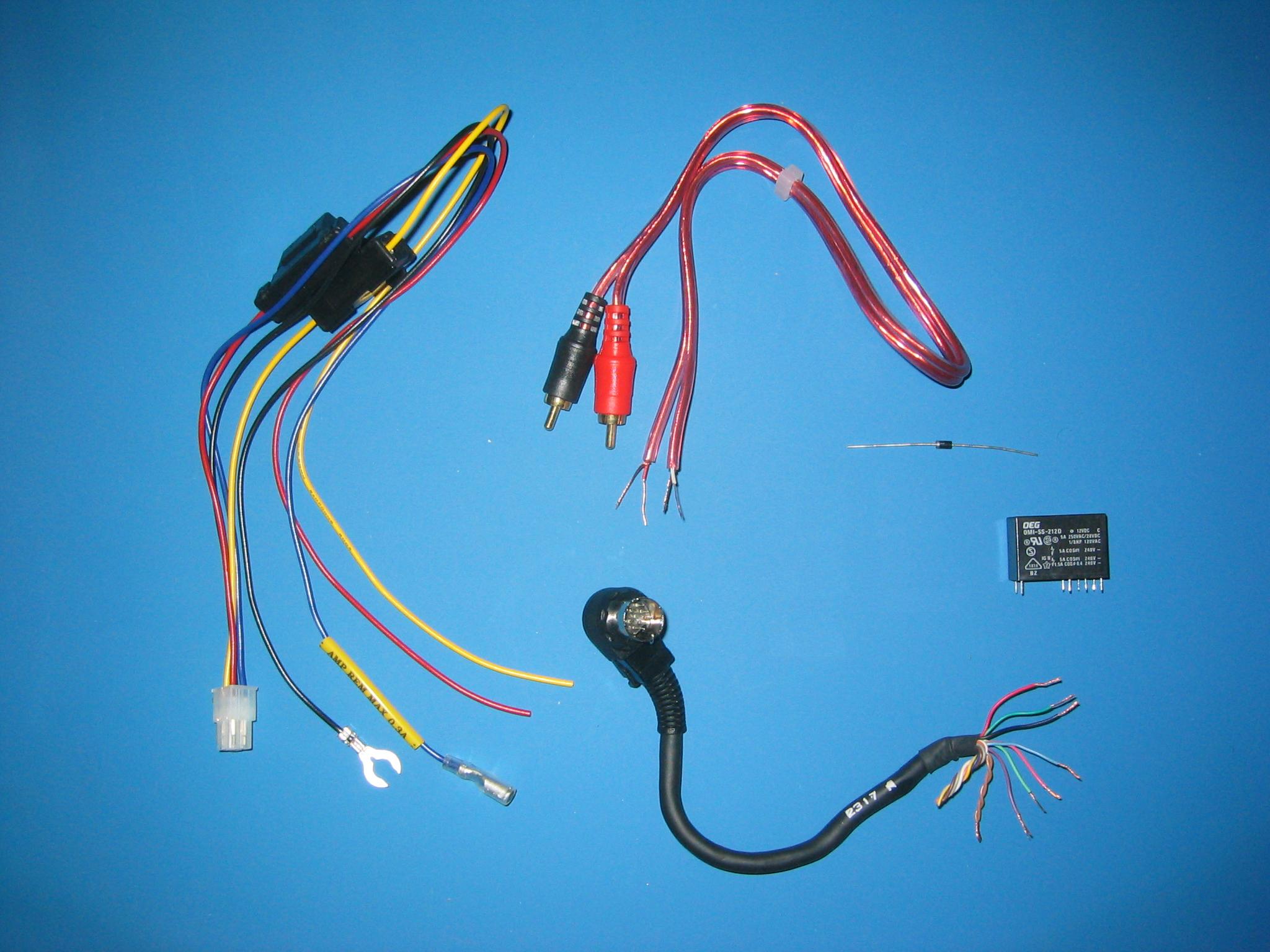
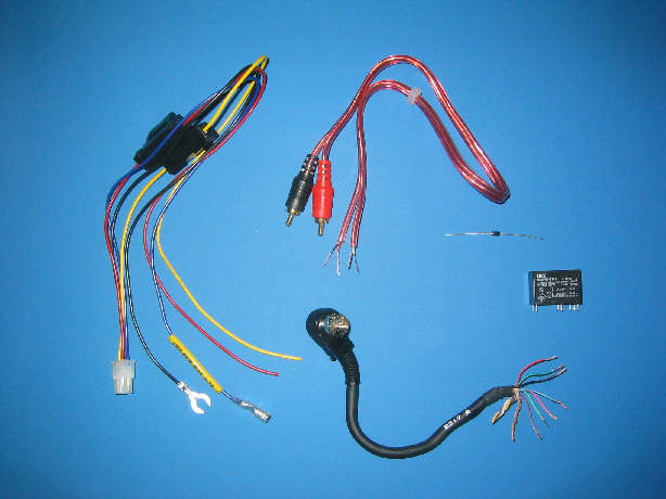
The first picture shows the key parts for my cable. The cable
bundle on the left is the original wiring that comes with the Sony CD
player (I bought mine new from Etronics.com). To save a little
effort, and to get a molded strain relief, I purchased an RCA patch
cable, then cut off one end. The shield of each conductor is
connected to ground, per the notes in the schematic. I used a
Radio Shack 276-1101 diode to protect the Sony from any reverse voltage
that can occur when the magnetic field on the relay's coil
collapses. I settled on the Radio Shack Double Pole Double Throw
275-249 relay; this one is kind of overkill for the low current of the
audio, but it's what I could easily get. I cannibalized the 13-pin
connector and pigtail from my failed OEM (Mazda/Panasonic) CD
Player.
Note: I've seen sources for new 13-pin connectors with pigtails in a
couple of places. As of this writing:
http://www.mfjenterprises.com/products/mfj-5213
(for $16)
and http://www.farallon.us/webstore/54.html,
which is $15 on
http://www.farallon.us
(search for item 8070).
If you're doing this, I would strongly recommend getting the connector
with pigtails. Those pins are pretty small and quite close
together; you'll save a lot of aggravation and time for the modest
additional cost.
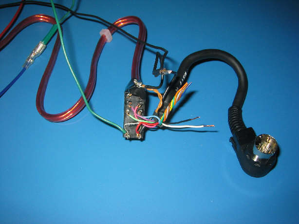
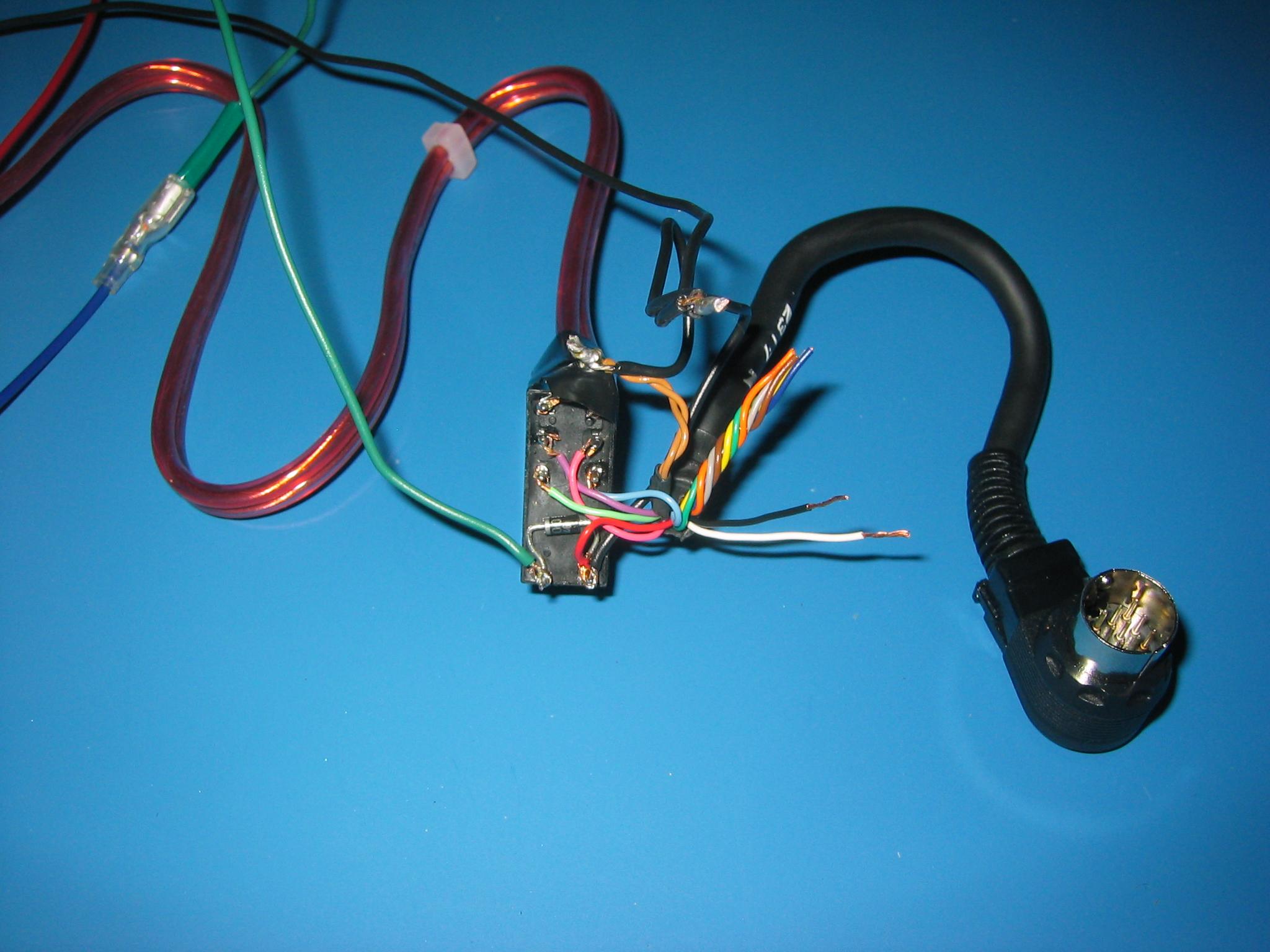
The picture above is a close-up of the connections to the relay.
I was able to
tuck the diode right against the body of the relay.
Note the orientation of the diode; it may appear to be "backwards"
in the diagram.
The diode is installed this way since
you don't want it to normally conduct;
only if there is reverse current from the relay, when
it is shut off, do you want to bleed off.
There is a bit of an explanation partway down this
page:
http://www.kpsec.freeuk.com/components/relay.htm.
The anode (black side) should
be connected to ground, and cathode (silver band) connected
to the +12.
Also keep in mind
when you're determining which color wire goes to which pin that the
13-pin plug is a mirror image of the socket (pin 1 starts on the left
side as you look at the plug pins, on the right side as you look at the
socket). My schematic is from the perspective of the
socket.
If you're doing as I did, and soldering the wiring directly to a
relay that is designed for solder-through installation on a circuit
board, be sure to affix something to the end of the relay pins.
They are fairly sharp, and with a modest amount of pressure, can poke
through typical electrical tape. I used some dense foam
insulation, and trimmed it to size and thickness.
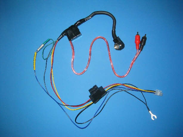
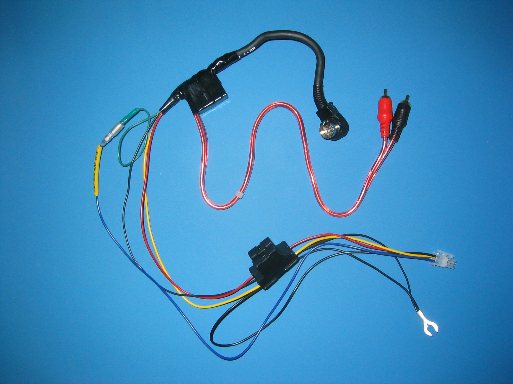
This is the completed wiring bundle. The 13-pin plug connects to
the HU, and supplies power to the Sony CD player. The RCA
connectors are connected to the line-out of the CD player. The
four-pin plug connects to the CD player. The ground spade
connects to the HU.
If I were making another one of these, I would shorten the length of
some of the wires a little. With the components removed from the
dash, it looks like there is lots of space to tuck cabling pieces
behind the devices. While this may be true, getting the wires
stuffed in "just so" is a lot harder than I would have thought.
It takes some patience and several tries to get everything reinserted
with just this minimal bundle. Folks with more goodies are in for
a more challenging time.
Questions or comments?
fosterm (at) sonic.net