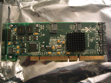
The RC4852 supports the extended 64-bit PCI-X bus, but works fine in
less expensive motherboards with 32-bit PCI bus. Five of the SATA
connectors are on the front, three on the back side of the board.
RAIDCore has chosen to give hardware assist just where it’s needed, and
puts most of their logic in the software that runs on the host
CPU. This design means that as you upgrade your CPU and
motherboard, you automatically upgrade the performance of your RAID
subsystem. It also means they should be able to more readily
enhance some of the subsystem’s capabilities, since doing so generally
won’t mean new hardware.
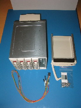
The SuperMicro CSE-M35T provides all the hardware and cables to install
in 5.25” drive bays and extend disk activity signals to LEDs.
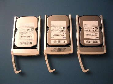
It was quick and simple to install the disks in the quick-release
brackets that are integral to the CSE-M35T. The SATA disks, like
SCA SCSI disks, provide power and data connections in a hot-plug
capable design. There is no cable or adapter between the chassis
bracket and the disk: the disk connects directly to the chassis
backplane.
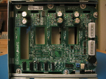
A look inside the back cover of the CSE-M35T shows dual power
connections, the SATA cable connectors, and header pins for disk
activity LEDs. Also note the large rectangular holes in the
printed circuit board. These are important: it’s how the air is
drawn off the drives and exhausted toward the back of the cabinet.
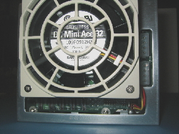
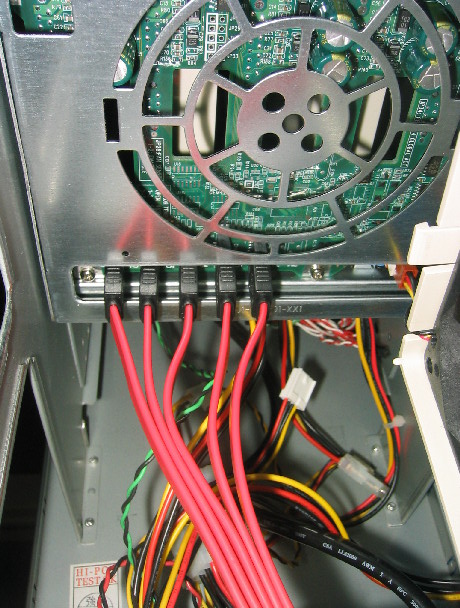
With the back cover and fan re-installed, you can still see the SATA
and power connections. The fan shown is Sanyo Denki 109P0912H202:
a 55 CFM fan that runs at 2900 rpm and produces a whopping 36
dbA. I cannot blame SuperMicro for choosing this fan. It
will definitely keep five drives running cool. They also probably
intend their chassis to spend most of it’s time in a noisy computer
room setting, not a quiet home office. I replaced the Sanyo Denki
with a SilenX SX-092-14. This fan only pushes 36 CFM, but also is
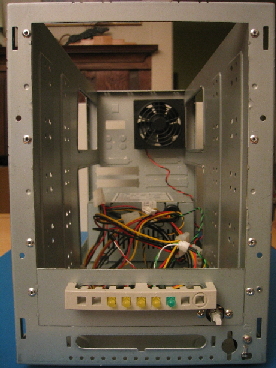
a nearly inaudible 14 dbA. I replaced the generic fan that came
in the salvaged cabinet with a SilenX 80mm thermistor controlled fan –
it will get noisy when it’s warm in the cabinet, so should function as
a early warning that I need to do something different.
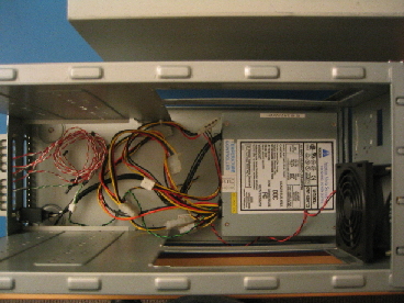
The cabinet was salvaged from some previous use, so had an ID switch
and SCSI-2 connectors, all of which were removed for this
application. I figured that even if I had to get a new power
supply, the $7 I spent was a great deal on the sheet metal frame
(ultimately, everything worked just fine - no replacement needed ).
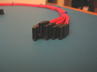
To reduce the unruly mess that all the thin, but stiff SATA cables
would create, I made a 5-cable bundle (I’ll make another 3-cable bundle
when the time comes to add a three drive chassis and disks). If
you’re doing this, be sure you line up the cable end keying, as shown
in this closeup of the end of the bundle. Also, take care if
you are using tie-wraps, as I did. They should be just snug, not
tight. Otherwise, you risk affecting signal integrity (RAIDCore
customer support confirms this). An alternative to tie-wraps
is electrical tape.
One end of the bundle connects to the backplane in the CSE-M35T
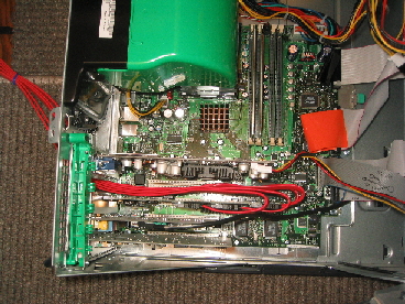
The other end of the bundle connects to the RC4852, installed in the PC
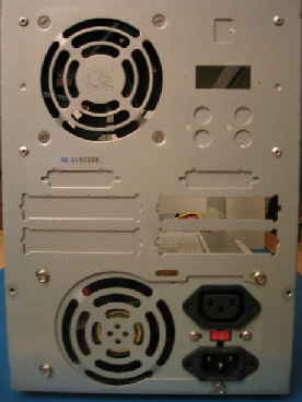
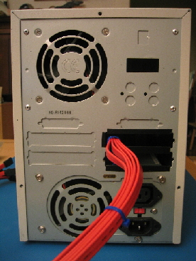
The back of the assembled cabinet shows the cable bundle passing
through one of the open slots previously used for a SCSI cable
connector.
I tie-wrapped the bundle to the cabinet at this opening, as a
strain relief.
I thought about using the 3ware SATA-to-firewire cable
adapters, so I didn’t have to have a single hard-to-disconnect cable
set chaining the PC and external cabinet together. Between not
having enough free PCI blanks in my PC and the additional problems the
extra cabling and connectors could cause me (not to mention the added
expense), I quickly extinguished the thought.
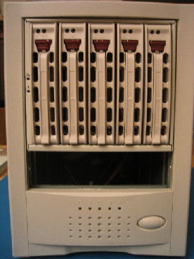
With the disks installed, the cabinet looks like it was made for
this. Leaving the (missing) blank open will help some with
airflow, and in this case, function is more important to me than
cosmetics.
Activating the Array – The Software
Installing the software from the CD went without a hitch. The
RC4852 comes with a comprehensive Users Guide (in PDF). Although
I was impatient, it was worth reading through it. They offer two
interfaces for array configuration, one BIOS level, the other a GUI
that runs under Windows. If you were setting up an array that was
going to comprise the system boot disk, you’d need to do the
configuration from the BIOS interface. Since I was just adding an
auxiliary drive, I was able to perform all the steps from the
GUI. I setup the RAID5 configuration to span across all three
disks. I had originally thought I’d be able to use their
“spanning spare” technology, but it turns out I’d need a fourth disk
for that. As easy as it is to get replacement disks, I think I
can risk running without a hot spare or spanned spare for now.
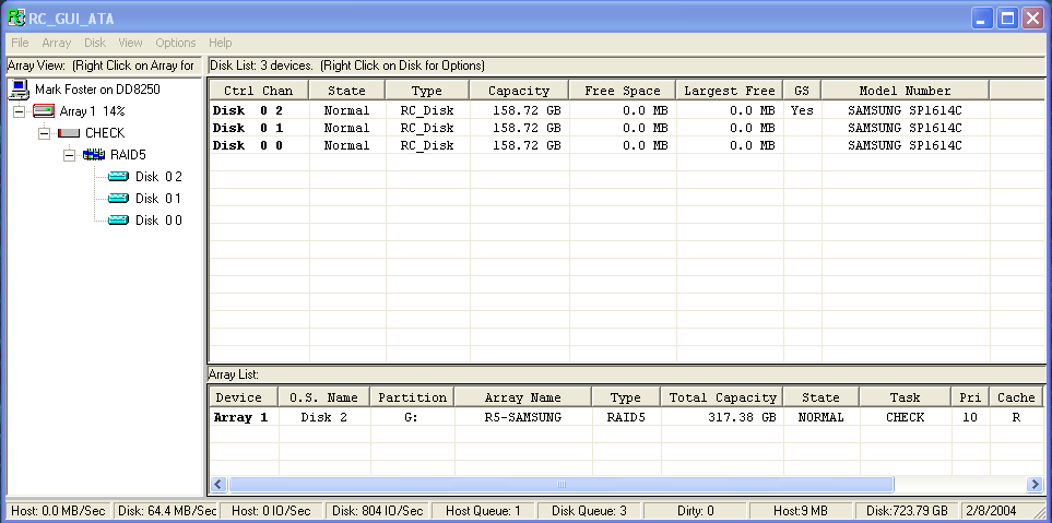
Once setup, I told it to initialize the three disks and create the
array. Be prepared for the time this process takes. It’s
analogous to a low-level format (even though that’s not what it’s
doing), and scales according to the size and number of disks. It
took about 8 hours on my setup. Once that completed, I decided to
run a “check consistency” (sometimes when working with fresh bits and
bolts, I tend to be paranoid). That took about 2.5 hours.
The check is in progress in this screenshot:
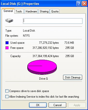
Then, I had Windows format the “disk”, the result is a single 295 GB
drive G:. Recall that in RAID5, one disk worth of capacity is
allocated to parity (even though the parity is striped across all the
disks). So, three 160 GB disks is really only 320 GB of space,
and with some filesystem overhead, 295 GB looks about right.
Time to exercise some of the features. I copied several GB’s
worth of content to the new filesystem, and began playback of the
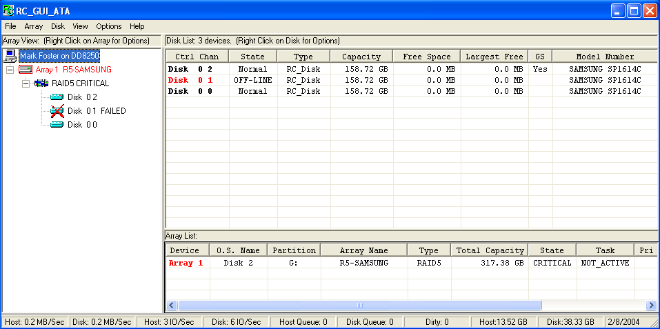
video. To simulate a genuine disk failure, I pulled the second
disk (“disk 01” in the array nomenclature). A popup box notified
of the status change, and a glance at the management GUI confirmed the
condition.
All the while, the video continued playing with no glitches or
hiccups. So far, so good. Now, simulating the “repair”.
I had thought that I’d be able to reinsert the disk, tell the
controller to “rescan” the drives, and I’d be quickly back in full
operation. I assumed this because I’d been careful not to write
anything to the disk during this failure. This simplistic view
turned out to be false. That’s okay, it’s just that recovery took
longer than I thought it might in this instance.
A reinsert of the disk generated a popup box.
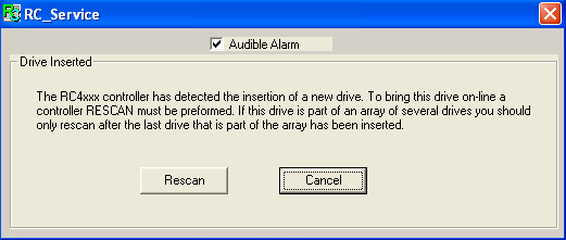
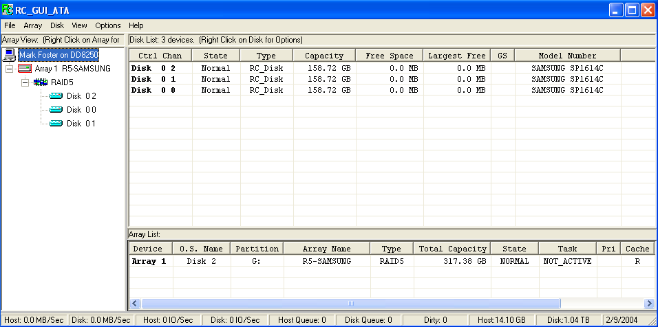
As instructed, I performed the rescan. The system sees the disk,
and recognizes that it is part of an array: note that Disk 01 shows
zero space available.
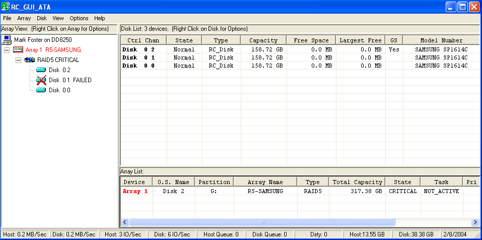
But, the array is still in critical state, and there is no active
rebuild or recovery task working toward fixing that state.
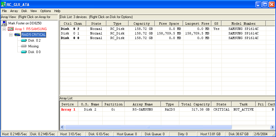
I proceeded to reinitialize Disk 01. This wipes out all the array
information on the disk, and thus, makes it look like an unused
disk. Doing so also changed the list of disks that the array knew
about: Disk 01 is now listed as “missing”.
I would have thought I could then request a “rebuild” of the array, but
either the sequence of events I had followed, or the support for that
(direct) approach isn’t fully there. In any case, I decided to
try the “transform” feature. I wanted to exercise this
functionality anyway, since I do expect to use it in the future when I
add disks to the array.
UPDATE (7/04): RAIDCore customer support (Jeff Huber) suggests that
I could have accomplished this step more easily by right clicking
on the failed disk, then selecting "initialize and set as ... spare".
![]()
Once I did a “commit” of this transformation, the online conversion
from the critical disk-missing array to the new three-disk
configuration commenced.
![]()
In about eight hours, the rebuild was finished, and all was well again
with the array.
For a significant portion of the time the rebuild was taking place, I
continued to use the system for text editing, email, and
browsing. I also periodically played some video content off the
array, watching and listening for glitches or hiccups. I didn’t
observe any. The cpu utilization during the rebuild was generally
about 20%.
I should also mention that during the rebuild, I had the array’s write
caching turned off. I did this for a couple of reasons. I
wanted to know a worst case scenario for a rebuild, and I wanted to see
how it impacted what I would consider typical use conditions if I left
write caching off all the time.
I’ve done some informal testing since the original configuration
testing, and the write caching seems to get about a 10-fold increase in
write speed. I haven’t taken the time to see if it provides a
similar speedup in the rebuild, but I suspect it would have a
substantial impact.
The Cost
At the outset, I wanted this to be an affordable solution. I
didn’t expect it to be low cost. One giant disk would have been much
less expensive.
| RAIDCore RC4852 | 350.00 |
| SuperMicro CSE-M35T | 150.00 |
| (3) Samsung SP1614C | 345.00 |
| (8) 1m SATA cables | 48.00 |
| (2) SilenX fans | 35.00 |
| 5-bay cabinet | 7.00 |
| TOTAL | 935.00 |
| As built $/GB for 320 GB capacity | 2.92 |
| (2) additional Samsung disks | 230.00 |
| TOTAL | 1165.00 |
| $/GB for 640 GB capacity | 1.82 |