GM IAC Motor
GM IAC Motor
01/12/2002 -
Started looking at using an GM IAC motor.
Wasn't sure if GM left current flowing through the windings when it was
not stepping or not. I suspected that they did but one schematic
I saw to drive one of these guys was setup so that only current flowed
when the UDN2916 PWM Motor Driver
was addressed. The surest way was to see what GM actually did.
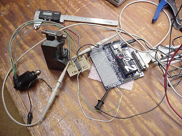
I have a 1988 Oldsmobile so a little poking around with the scope answered
my questions.
The IAC stepper motor that I scrounged from a wrecking
yard and the one on my Olds look exactly identical. I didn't pull
it off the car but I suspect the pintle is the same also. Got to
love GM. One difference was in the wiring harness though. They
both had the same color coded wires put some of the positions were swapped.
|
|
Old's | Junk Yard's |
|---|---|---|
| A | Green/Black | Green/White |
| B | Green/White | Green/Black |
| C | Blue/Black | Blue/White |
| D | Blue/White | Blue/Black |
How it reacted to key on and start running:
  At key on the position of the motor did not change.
    DC Current was applied as:
      A - +12v
      B - ground
      C - +12v
      D - ground
  Soon after the motor was started the pintle was stepped outward (reducing
    air flow). The motor was cold and idling too fast.  The cars IAC was
    disconnected and I was looking at my unit externally.
  At key off the pintle was stepped backwards from where it was a set number
    of steps.  Don't know how many though.  Probably a parking position
    getting ready for the next start up.
I had thought that the algorithm would find a home position and count outwards from there for an engine start but that doesn't seem to be what happens. It just retracts from where it was a number of steps and the next engine start is done from there.
Got curious so I took it apart to see what is inside.
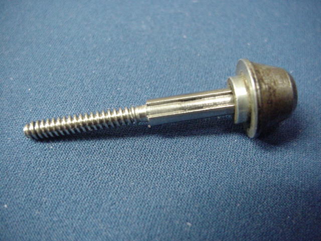
This is the moveable pintle. The threads are 1 turn per mm. Diameter of the threaded portion is 3.5mm. If you over drive the assembly this little guy shoots out. The only stop is the pintle seat.
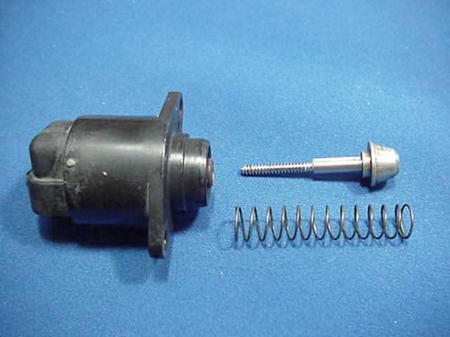
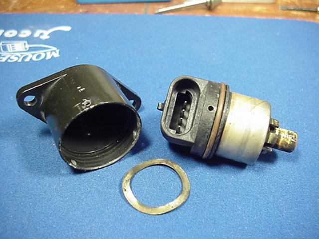
Getting this guy apart was interesting. After pulling the three (3) small pins that held the unit together you need to slide the motor assembly out. That brown O-ring is really tuff and didn't want to give up. Make sure you push the motor back as you take it apart or you will break the VERY small wires connecting it to the socket.
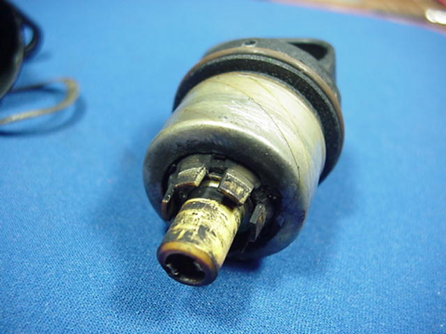
This is the actual motor. After all the work
to get it apart there wasn't much to see.
A couple of numbers:
    1 thread per mm
   24 steps per mm extension
  310 steps and pintle hyper extends
A few more wave forms can be found here.
Don't know for sure what direction the motor was operating with these.