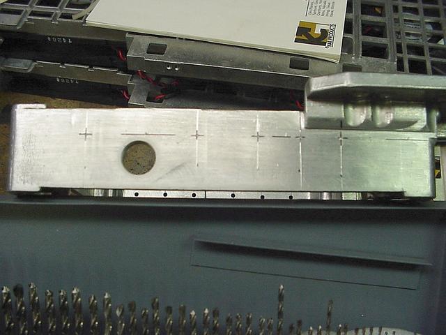
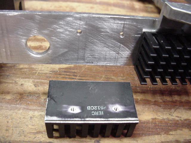
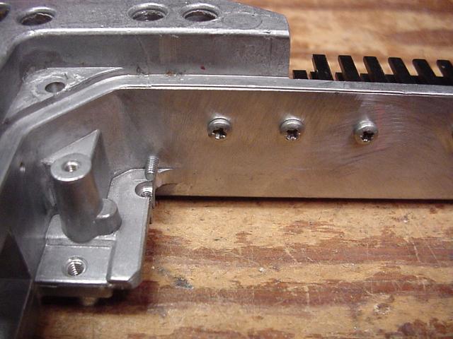
| Started by determining the locations
of the TO-220 mounting holes. Next drilled them for the pilot
holes. |
|
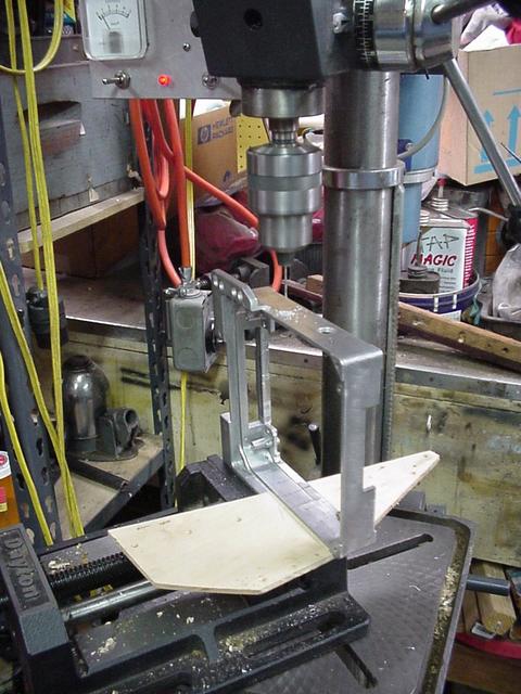
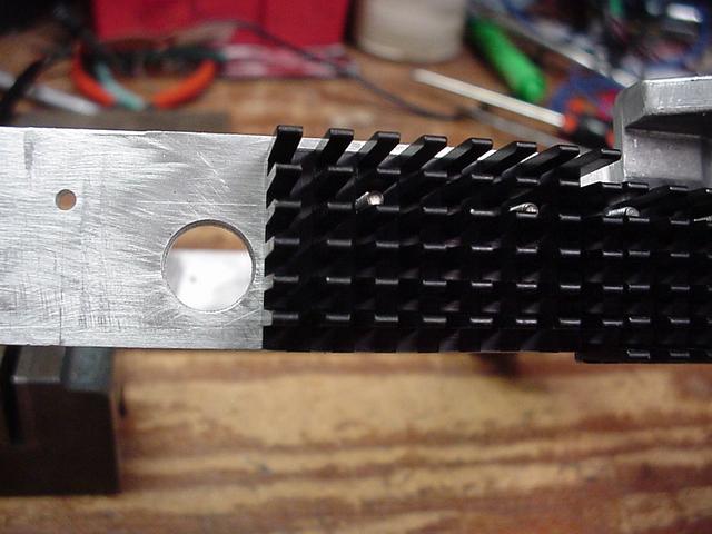
| The second regulator is close to the
front of case requiring the first heat sink segment to be moved to the
rear to get enough material to tap into. Also used a third screw up
front to help keep the heat sink flat against the case wall. |
|
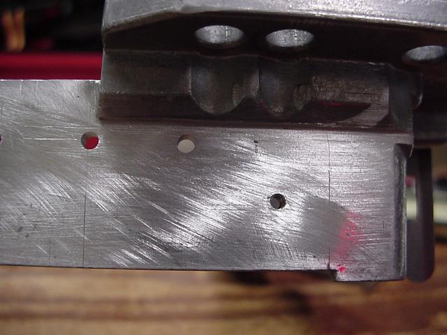
| The first segment in place. |
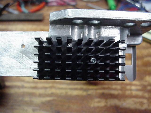 |
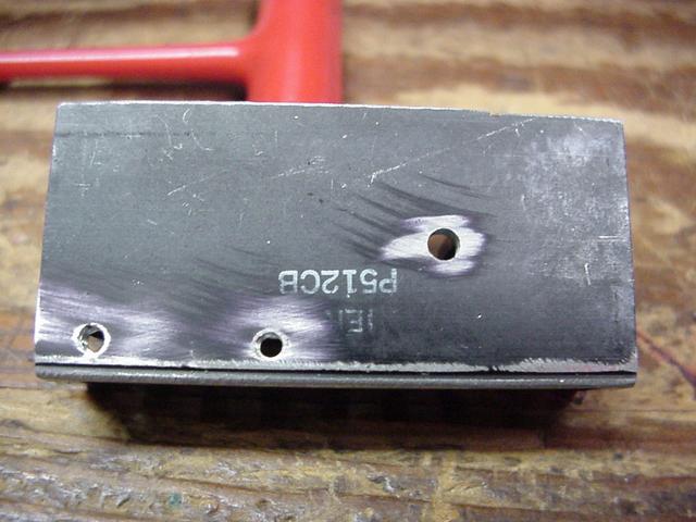
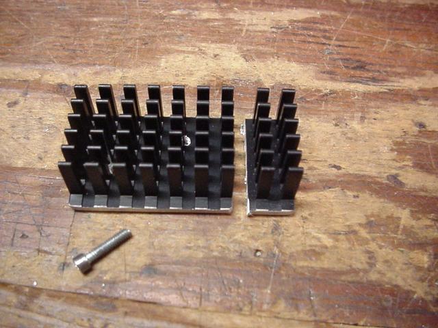
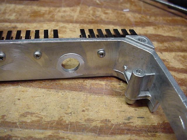
| Because the first segment was pushed back
had to take a row of fins off the middle segment so it would not over
lapped the exit hole in the case side.
|
 |
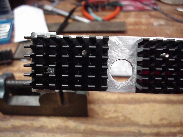
| Middle segment drilled and tapped, and mounted into position. |
|
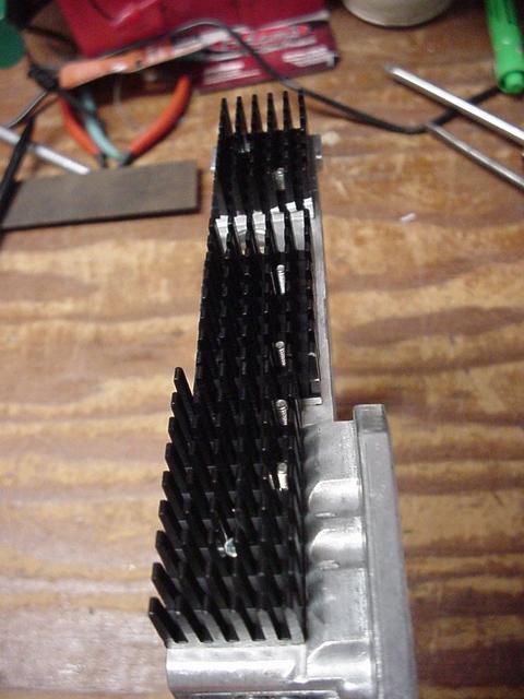
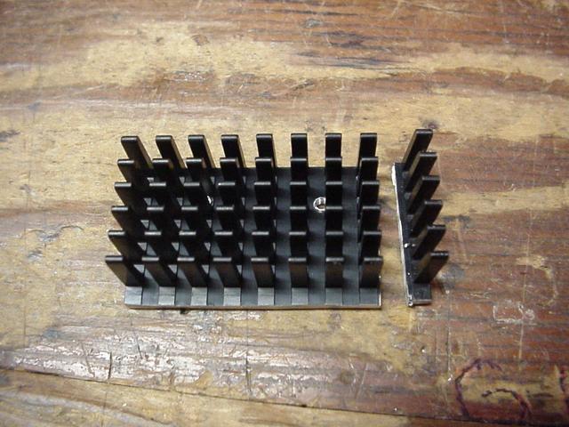
| The rear segment had to loose a couple of
rows so it wouldn't stick out past the end of the case. Being there
was only one transistor I needed another mounting screw to hold it in
place also. |
|
| An inside view.
|
|
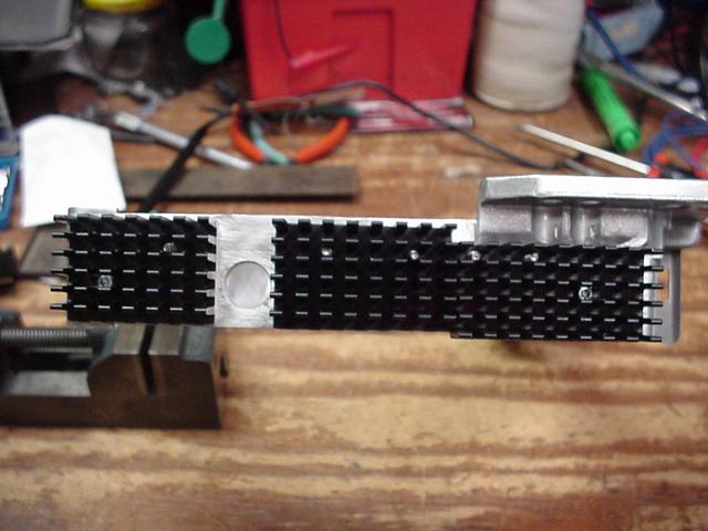
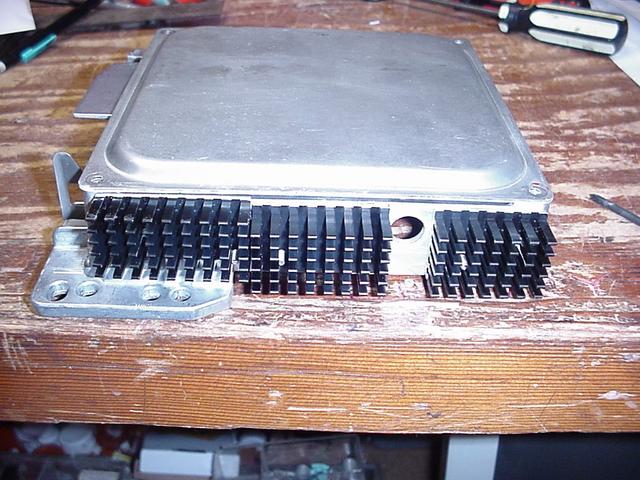
| All three segment in place. Didn't loose any fins to mounting screw positions either.
|
|
| With the lid on just to make sure all clears.
|
|