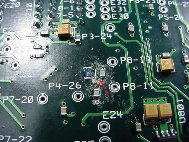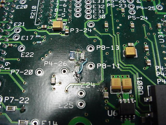
While turning on board #3 I noticed that the 4 MHz oscillator on U700 (TPIC8101) Knock DSP was lazy coming on. The first two units I checked to see that it was oscillating but being that we haven't implemented the knock sensor yet didn't pay enough attention to how it turned on. For some reason #3 had a harder time oscillating than the other two boards. Probably a little less gain in the inverter that makes up the oscillator. After changing the crystal and verifying the associated components took a closer look at the layout. The Texas Instrument data-sheet was useless on how to configure this circuit so I had look at the Intersel data-sheet for the HIP9011 part which TI copied. They show a layout but it was poorly drawn (lot to be said on just how a schematic is drawn) and I mis-read it in a way where I got one of the caps across the crystal instead of to ground. Looking at it now it is clear that the way it was laid out was wrong but missed it then.