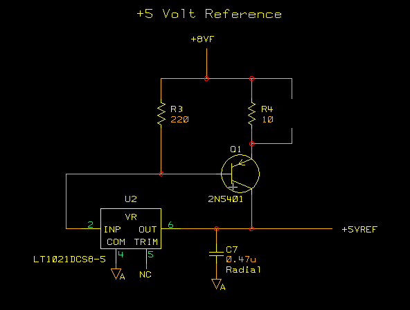
Original +5 volt precision reference circuit.
A few short comings in the precision +5 volt reference have surfaced. The first is the lack of current limiting. If a short should develop on the reference somewhere the current boost transistor would dissipate too much power and destroy itself. As it turns out it is relative easy to add current limiting to the existing circuit. An LED across the R3 would divert base current from the pass transistor when the voltage across the emitter resistor reached approximately .7 volts. This voltage drop along with the forward bias voltage on the transistor would start to turn on the LED and divert base current thus turning off the transistor. The problem that arose next was was to activate the current limiting action at a reasonable level, say 100 ma, the voltage at the input to the LT1021 reference IC would drop too low and the regulator would start to drop out. Reducing the emitter resistor then the power dissipation in the pass transistor would be too high under a shorted condition and we were right back to our starting point with a damaged transistor. A fold-back circuit was needed. Several designs were tried with the below version working the best. This is still prototyped on the PCB and hasn't been committed to yet but it looks like it may be the final solution on this revision of the PCB.

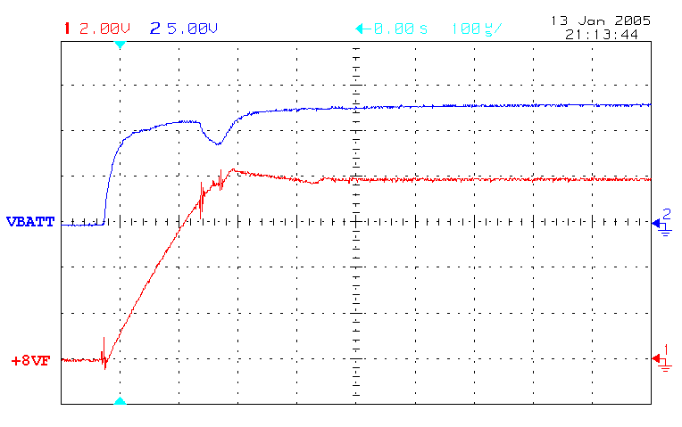
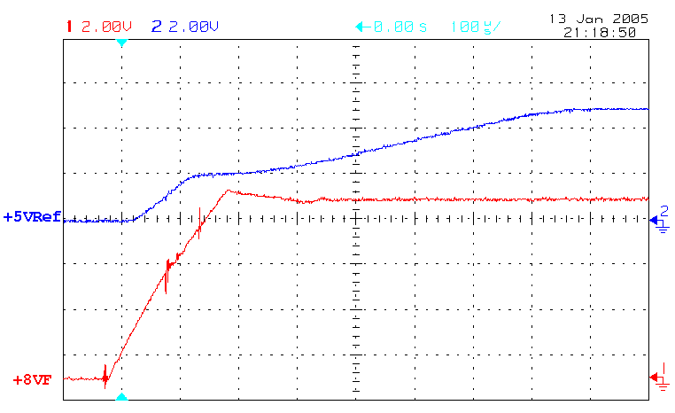
50ma load R4 = 10 ohms
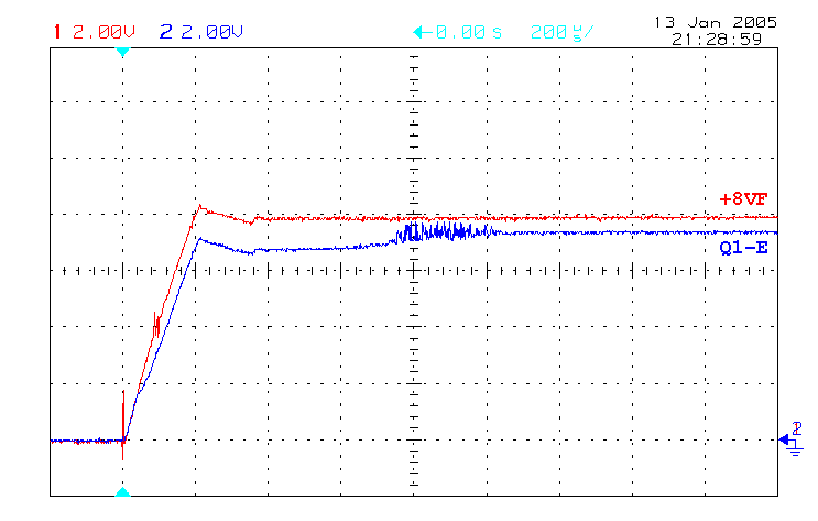
50ma load R4 = 10 ohms
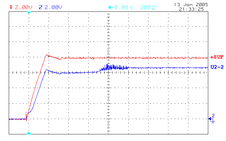
50ma load R4 = 10 ohms
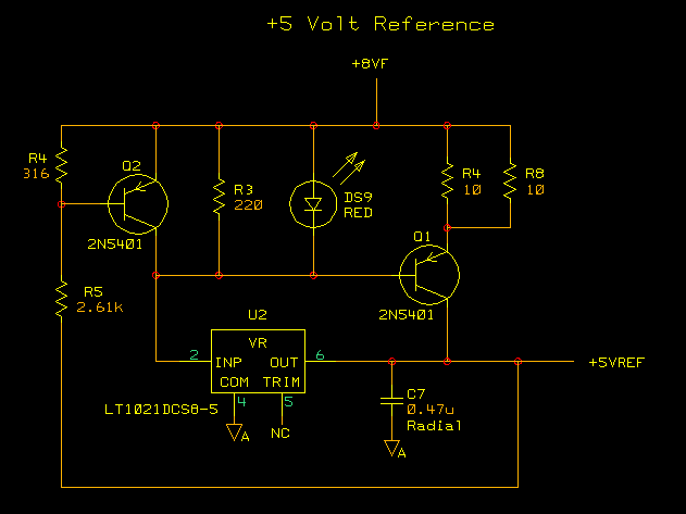
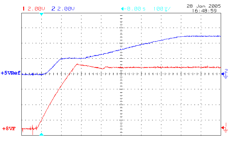
R4 = 5 ohms
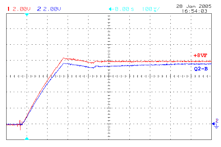
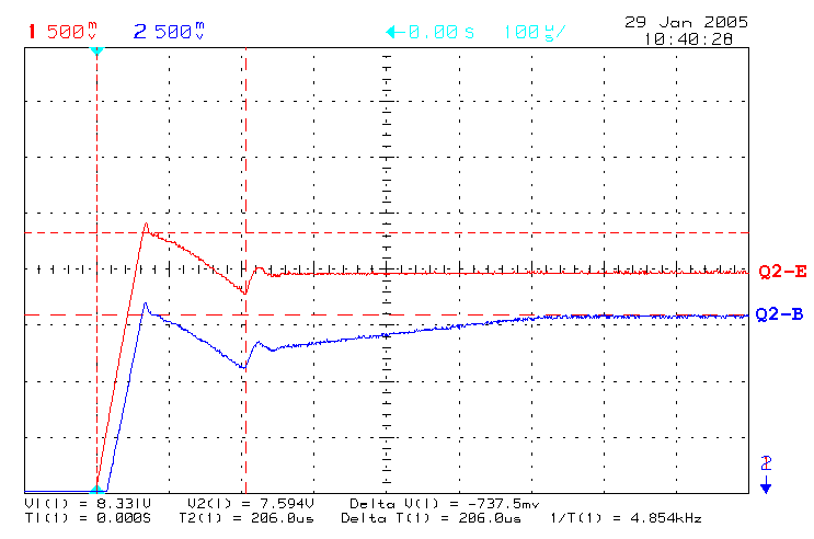
105ma load R4 = 5 ohms
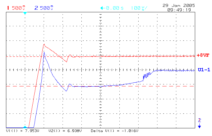
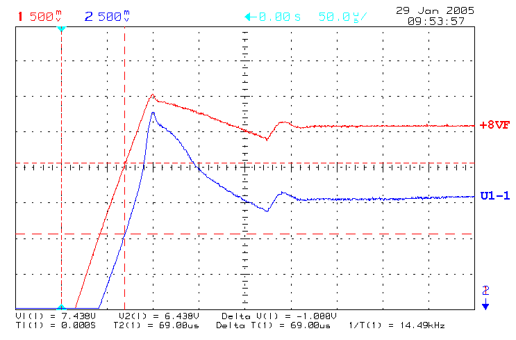
105ma load R4 = 5 ohms
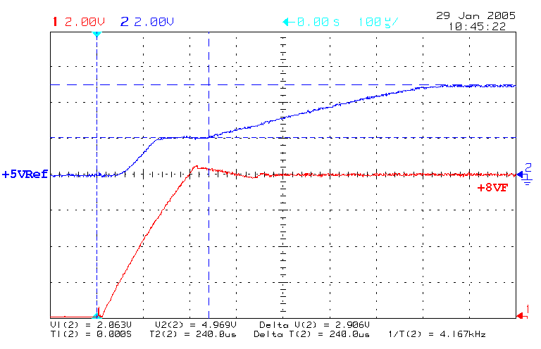
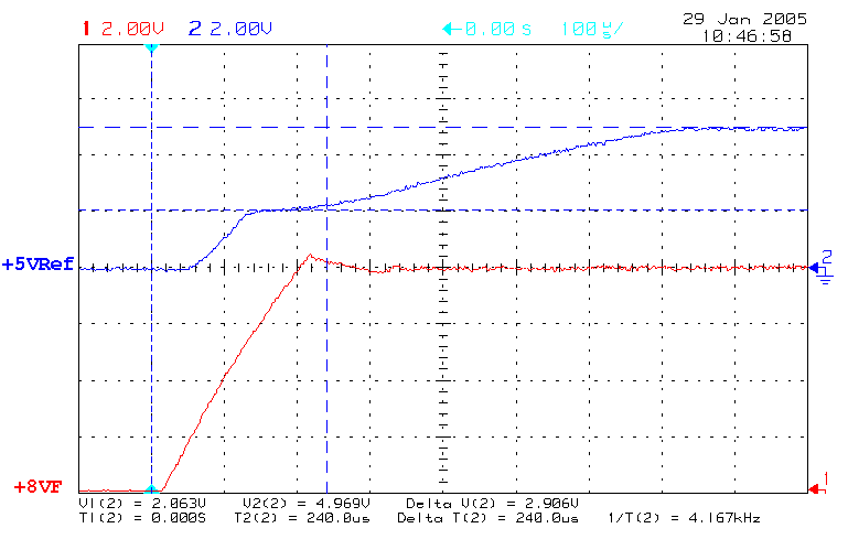
105ma load R4 = 5 ohms