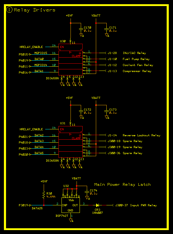
Relay Drivers - Block I
NOTE: Modified 03/30/05

This circuit is designed to
control up to nine (9) external relays. Eight outputs are driven
by two DS3658N
quad High Current low side peripheral drivers. They are designed to drive a relay which has one side attached to the vehicle's
battery. Inductive feedback clamping diodes are incorporated in the device so no external diodes are required. Looking at what is
already assigned the top three are pretty self explanatory. You might wonder what the compressor and reverse lockout are about.
Well in the '34 there are two auxiliary air pumps. One is a vacuum pump to assist with the power brakes and several other vacuum
driven systems in the car. The other is a Thompson 150 lb. capable air compressor that runs my second horn. Lets just say
that I am not invisible anymore, or at least not unheard anymore. The Reverse Lockout one is to control the vacuum motor that locks out
reverse on the unbelievably poorly designed Hurst shifter (which the Mr. Gasket group has destroyed along with all other classic product
lines they absorbed and ran into the ground) on my Richmond 5 speed transmission. The vehicle speed information will come from the
vehicle speed input circuitry (Block T). The last three are free at the moment.
The final driver is designed to keep the power input relay on after the power is removed by the ignition
switch. A BSP742T smart high side driver does that job for us. This driver feeds power through CR3 to the highs side of the
main power relay feeding the ECM. Another external switching diode in series with the switched power from the ignition switch is
also employed. This gives us a wired OR situation where either the ignition switch can power up the ECM or the ECM itself can keep the
power applied to it. The reason we went this route was to always assure an orderly power down. We do not have any non-volatile RAM
other than a couple EEPROMs (Block L). We have future plans to write back some currently learned information
to the EEPROM. This means we need to keep power to the ECM after the ignition switch is turned off. Also this may be able to help
with some re-start situations because the ECM will always know what is going on. After some predetermined time of inactivity the ECM
will power itself down. This is kind of a weird way of doing all this but it was driven by trying to stay compatible the the original
Edelbrock Weber wiring.

