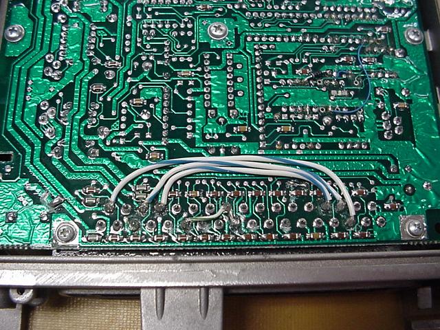
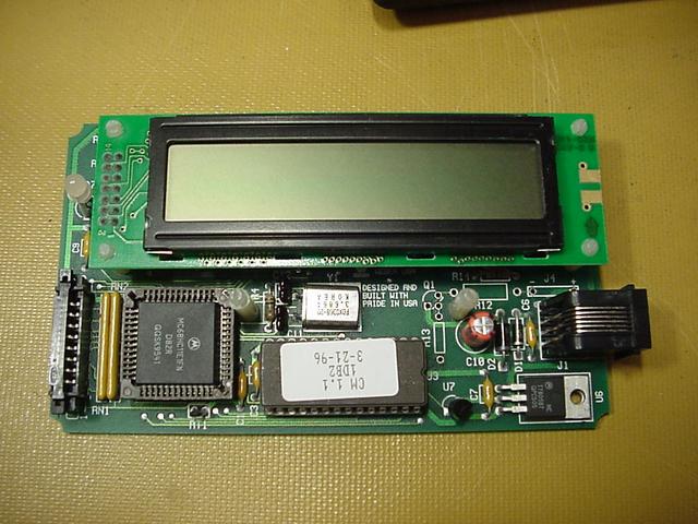
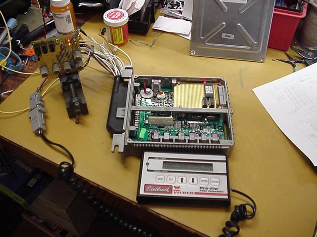
One of our design goals here was to set this new ECM and wiring up in such a way that the original Weber ECM would still work in the vehicles. So one thing that needed to happen was that the original Weber ECM would need some modifications to be compatable. For instance the new ECM is fully sequential and the Weber fired a pair of injectors at a time (the Weber ECM originally was for a four cylinder car). This required that the original injector driver outputs to be jumped to the newly defined connector pins. There were numerous other pins that also needed to be cleared and sometimes connected else were. Another thing that we did is to remove the double inversion in the serial lines. The original Weber setup inverted the serial lines for some reason so a special cable was required to connect a laptop to the ECM. On the new ECM we designed our serial interface with standard polarity. We wanted to use the Edelbrock supplied hand held with our new ECM so we need to remove the extra inversion from both units.
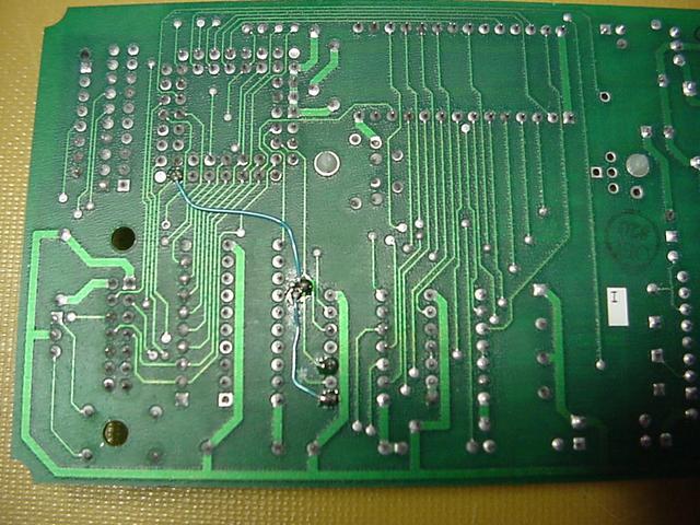
Notes on main ECM plug wiring....

Input Pin:
1   Gnd - No change
2   O2  - No change
3   Inj #8 - Was Crank Trigger Return........
         ECM  - Cut ground and tie to J1-35
         Conn - Brown-16 to this pin (J1-3)
                Wire that was on this pin (Yellow-18) to J1-5
4   CAM Index - No Change
5   CAM/Crank Return -
         Conn - Leave wire that is now on it and attach wire
                 that was on J1-3 to it.
6   O2 return -
         ECM  - Assure this in is clear
         Conn - Green-18 to this pin
7   Oil Sensor -
         ECM  - Assure this pin is clear
         Conn - White-18 - Right Rocker to Dash & oil pressure gauge
8   Serial Receive Data -
         ECM  - Remove inversion
         Conn - No Change
9   Speedo Input -
         ECM  - Assure this pin is clear
         Conn - Blue-18 from speedo pickup
10  Fuel Pump Relay -
         ECM  - Clear pin then tie to J1-28, org Main Power Relay
                Also jumper to J1-13
         Conn - Move Tan/Wht wire from J1-28 to J1-10
                 Will be using the original relay as the fuel pump
                 only relay now.
11  Sensor Ground Return - No change
12  Coolant Fan Relay -
         ECM  - Assure this pin is clear
         Conn - Yellow-18 wire up right rocker to front coolant relay
13  Compressor Relay -
         ECM  - Assure this pin is clear. Jumper to J1-10 & J1-28.
         Conn - Yellow-18 to low side of compressor activate relay.
                This relay will supply power to the SPDT switch in
                 the battery compartment which directs control power
                 to the compressor relay and it will supply the control
                 signal to the vacuum pump control circuit.
14  Reverse Lockout Relay -
         ECM  - Assure this pin is clear
         Conn - Yellow-18 to reverse vacuum solenoid
15  MAP Sensor - No change
16  INJ-#5 -
         ECM  - Clear this pin and tie to J1-18
         Conn - Move wire that was on J1-18 to this pin (screwed up!)
17  TPS Sensor - No Change
18  INJ-#6 -
         ECM  - No Change
         Conn - Move original wire (Black/Red) to J1-16
                Blue-16 to this pin
19  Gnd - No change
20  ECU Power - No change
21  INJ-#3 -
         ECM  - Assure this pin clear and tie to J1-33
         Conn - Black-16 tied to this pin
22  INJ-#2 -
         ECM  - Assure this pin clear and tie to J1-32
         Conn - Red-16 tied to this pin
23  Crank Trigger+  - No change
24  Key on Sense -
         ECM  - Assure this pin is clear.  Internally need to tie
                 47 ohm emitter resistor to ground.
         Conn - Blue-18 to ignition switch - pre diode!
                Remove the wire that was there and leave free. This wire
                 will cause a ground loop if tied to ground, so what to do
                 with it??????????????
                 Removed wire (blk-18) from plug trying to get enough
                  room to install hood.
25  SA Output - Ignition Amp Trigger -
         ECM  - Install a 2.7k resistor to +5 Vref
         Conn - Remove 2.7k to +5 Vref
26  Ignition B spare output
         ECM  - Ok to leave as is.
         Conn - Orange-18 wire out and mark as spare ignition output
27  Serial Transmit Data -
         ECM  - Remove inversion from signal
         Conn - No change
28  Injector/IAC Relay
         ECM  - Tie this pin to J1-10 and J1-13
         Conn - Green-18 wire to new INJ/IAC Relay
29  COOL Sensor - No change
30  +5 Vref Output - No change
31  MAT Sensor - No Change
32  INJ-#7 -
         ECM  - Tie this pin to J1-22
         Conn - No change
33  INJ-#4 -
         ECM  - Tie this to pin to J1-21
         Conn - No change
34  IAC Motor - No change
35  INJ-#1 -
         ECM  - Tie this pin to J1-3
         Conn - No change
| Pin | ECM #IAW4W6 | With Crank Trigger | MPC555 ECM |
|---|---|---|---|
| 1 | Ground | Ground | Ground |
| 2 | O2 Sensor | O2 Sensor | O2 Sensor |
| 3 | N/C - (Gnd) | Crank Trigger- (Gnd) | Injector #8 |
| 4 | N/C - (magnetic input) | CAM Position+ | CAM Position+ |
| 5 | Dist Return (Gnd) | CAM Position- (Gnd) | CAM/Crank Return (Gnd) |
| 6 | N/C - (Gnd) | N/C - (Gnd) | O2 Ret to Differential NBO2 |
| 7 | N/C - (CA3262E-8) | N/C - (CA3262E-8) | Oil Pressure Sensor |
| 8 | ECM Serial RX | ECM Serial RX | ECM Serial RX |
| 9 | N/C - AN1 Input | N/C - AN1 Input | Speedometer Input |
| 10 | Diode Protection | Diode Protection | Fuel Pump Relay |
| 11 | Sense Return (Gnd) | Sense Return (Gnd) | Sense Return (Gnd) |
| 12 | N/C - (CA3262E-3) | N/C - (CA3262E-3) | Coolant Fan Relay |
| 13 | N/C - (PAL-2 input) | N/C - (PAL-2 input) | Compressor Relay |
| 14 | N/C - (PAL-1 input) | N/C - (PAL-1 input) | Reverse Lockout Relay |
| 15 | MAP Sensor+ | MAP Sensor+ | MAP Sensor+ |
| 16 | N/C - (Current Driver) | N/C - (Current Driver) | Injector #5 |
| 17 | TPS Sensor+ | TPS Sensor+ | TPS Sensor+ |
| 18 | INJ-B (6&5) | INJ-B (6&5) | Injector #6 |
| 19 | Ground | Ground | Ground |
| 20 | ECM Power (+12 Relay) | ECM Power (+12 Relay) | ECM Power (+12 Relay) |
| 21 | N/C - (A/C sense) | N/C - (A/C sense) | Injector #3 |
| 22 | N/C - (HY2 / AN0) | N/C - (HY2 / AN0) | Injector #2 |
| 23 | Dist Trigger+ | Crank Trigger+ | Crank Trigger+ |
| 24 | Ignition Return (SA-) | Ignition Return (SA-) | Key On Sense |
| 25 | Ignition Output (SA+) | Ignition Output (SA+) | Ignition Output (SA+) |
| 26 | N/C - Ignition Output | N/C - Ignition Output | Ignition B Output (spare) |
| 27 | ECM Serial TX | ECM Serial TX | ECM Serial TX |
| 28 | Fuel Pump Relay | Fuel Pump Relay | Injector/IAC Power Relay |
| 29 | COOL Temp Sensor | COOL Temp Sensor | COOL Temp sensor |
| 30 | +5 volt Reference | +5 volt Reference | +5 volt Reference |
| 31 | MAT Sensor+ | MAT Sensor+ | MAT Sensor+ |
| 32 | INJ-D (2&7) | INJ-D (2&7) | Injector #7 |
| 33 | INJ-C (4&3) | INJ-C (4&3) | Injector #4 |
| 34 | IAC Motor | IAC Motor | IAC Motor |
| 35 | INJ-A (1&8) | INJ-A (1&8) | Injector #1 |