RE3 Disciplined Frequency Reference with OCXO Support
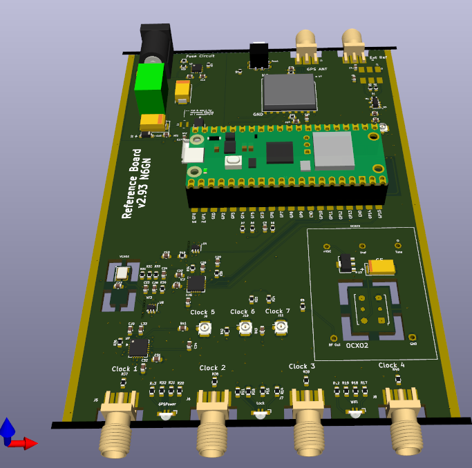
From the original RE to the latest version, these
disciplined REferences have had the primary objective to be
very low cost, accurate and high value devices for
synchronizing amateur radio communications equipment. LF
through VHF communications by way of the ionosphere has been a
particular target. Design choices have consistently
favored low cost above numerical performance as long as
it exceeds that which is useful for these radio
applications. These designs have proven themselves to
meet these objectives well.
It has been suggested that v1 and v2
"under-perform" because phase noise is higher than other, more
expensive, disciplined references that are commercially
available. Because v2 does meet the original goals of the
project to be very economical and work "well enough" for any
foreseeable amateur radio LF-VHF uses involving the
ionosphere, a 'better' version has not previously been
offered. The total parts cost for that entire PCB, enclosure,
and all other parts meet the goals well. Without US tariff
penalties, projected total cost is < US$50 for small
quantities and is deemed part of its "performance".
Fundamentally, beyond the disciplining PLL 's
bandwidth, a disciplined reference is no better than the local
reference oscillator being disciplined. In v2 that was a VCXO -
currently costing only US$1.54. Using a low-cost GNSS module as the
disciplining source, the possible bandwidth is quite limited. This
is because internal algorithmic phase corrections performed by
the module's code inject small phase steps in the disciplining time
pulse as that module's local TCXO is kept synchronous with GPS time.
"Time keeping" versions of GNSS modules which avoid these phase
corrections are available but are either more expensive or require
proprietary code. However, as described for forseeable and
known LF-VHF communications applications there should be no
discernible difference with this design compared to more costly
solutions, except for its much lower cost and extended features.
v3 is an increment of the v2 design. It does NOT
meet the lowest cost, high value goals of the original v1 and v2
projects. Instead it allows for internal or external
OCXOs. This can easily double the total component
cost. One improvement it can offer is stand-alone
operation - operation not requiring a GPS antenna. While the
most precise OCXO mode is disciplined by way of a frequency locked
loop (FLL) to potentially provide sub-ppb accuracy, that too uses
the GNSS constellation and module for discipline. However if a
high quality (expensive) OCXO such as the HP10811D is used,
once calibrated, it is possible to operate v3 for extended periods
of time without GNSS required. For some amateur
applications this could be a benefit worth the significant added
component cost.
Even so, the v3 design may be produced without the
addition of an internal OCXO. This moves the functionality
back to that of v2 but keeps the possibility of using an external
OCXO, if desired. The incremental component cost to build v3
rather than v2 is quite low so this design may be a preferred one
for many builders. The KiCad files below already DO NOT include one
of the two internal OCXO options so nothing need be done to build
and assemble an "OCXO-less" v3. If an internal OCXO is
desired, that would normally be ordered separately and added at
final assembly time. The ocxo131-100 option would
normally be purchased from eBay while the three components for the
ECOC-9775-VC option would be purchased from normal vendors such as
Mouser or Digikey. While raising the total
cost of the OCXO option, providing the design in this manner
makes the most economical version automatic while allowing the user
to option-in the OCXO of choice, if so desired. It's also possible
to assemble the PCB with no VCXO or PLL components. If the
result is only intended to operate with either an internal or
external OCXO, this may also be a very cost effective option having
quite good phase noise performance.
A careful study has not yet been made but it appears
that the Si5351-C synthesizer may be the limiting component. A
measurement provided below indicates that this limit may be near
-115 dBC at 100 Hz offset from the carrier, when normalized to 10
MHz.
Features & Improvements
- May use either an internal or external OCXO to provide improved phase noise and long term stability
- Can operate apart from any GNSS connection - continuous antenna connection may not be necessary
- Provides up to 7 configurable user outputs, master clock for HF transceiver or SDR
- Implements Continuous Fractions algorithm for essentially perfect frequency accuracy
- GNSS satellite or local 10 MHz frequency reference
- Flexible supply 8-30 VDC
- Typically better than .1 ppb, .00000001% long-term accuracy and stability
- WiFi web Interface - works with Windows, Apple or Linux systems.
- Common SDR and HF transceiver Frequency presets
-
Connections:
- SMA: GNSS Antenna
- External 10 MHz reference
- Seven SMA:User Selectable outputs 4 kHz to 225* MHz
- 2.1mm power barrel connector
- Four-layer, through-hole plated, silk-screen printed PCBs
- Aluminum enclosure
Example Web Interface

OCXO Monitor and Control page, generally after the
fashion of VE2ZAZ which it is patterned after.
HP10811D OCXO with FLL discipline. After warmup and
settling this is showing ~20 parts-per-trillion (ppt) accuracy.
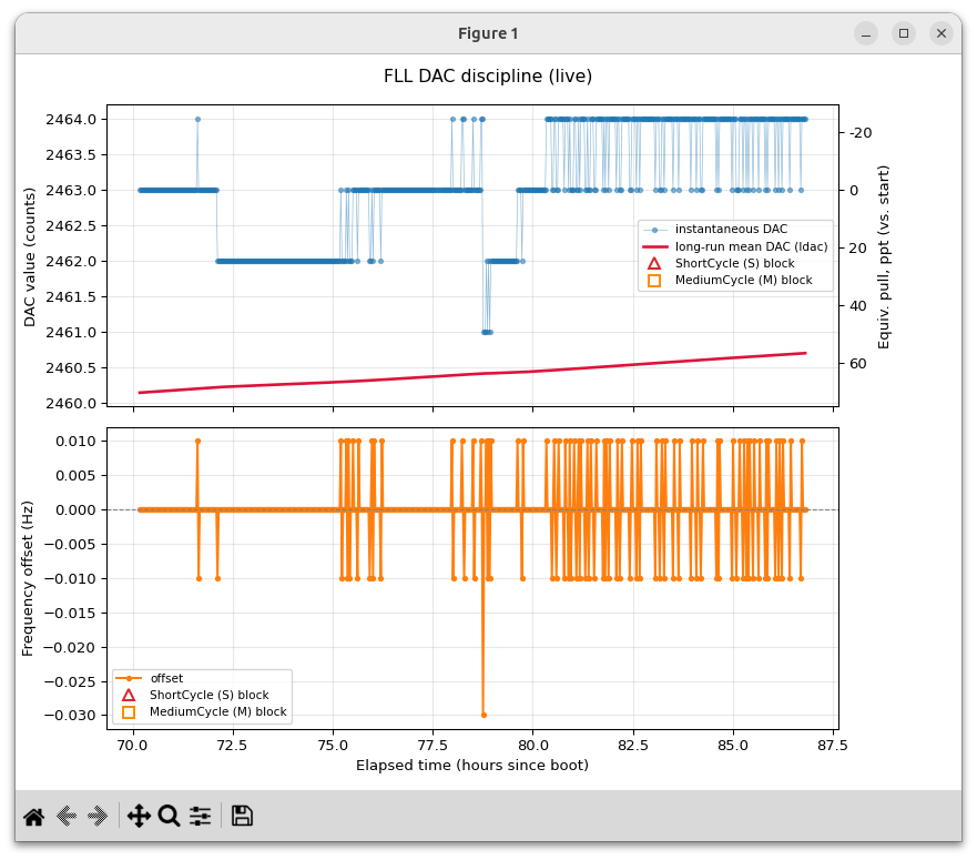
The plot below shows an Isotemp OCXO in FLL mode
measured over about three days time.
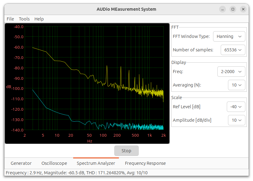
Blue trace is an unconnected 2nd audio channel
indicating measurement system noise floor.

This next plot shows REference v3 prototype using an
external Isotemp OCXOin FLL mode compared with Bodnar 'Mini at 100
MHz'.
This indicates about -95 dBC phase noise at 100 Hz offset from the
carrier, or -115 dBC when normalized to 10 MHz.
Measurement was made using a doubly balanced mixer as phase comparator
and with a Berringer UMC202HD USB audio interface. This measurement
cannot distinguish contributions from either source However phase
rotation verified to be from the Bodnar GPSDO causes the display to go
in and out of quadrature every few seconds. This is likely due to the
comparatively small lock bandwidth of the Bodnar/GNSS system. It
is not evident when the REference is compared with high quality OCXOs.
Blue trace is an unconnected 2nd audio channel
indicating measurement system noise floor.
Further measurements must be made to isolate
contributions and to determine whether any of these imperfections are
detectable when measuring any narrowband communications systems such
as WSPR and FST4W below VHF frequencies.
|
||||
Item Description |
Provider |
|
Notes |
Approximate Material Cost(excludes setup fees and shipping) |
Assembled RE3 PCBand Front&Rear Panels |
A newer,
not-yet-fabricated-and-tested version is now available as
KiCad filesUse the 'Production'
sub-directory to obtain .zip (Gerber), .bom and position.csv
files for JLCPCB fabrication.
|
US$40 | ||
| 2 x 20p CPU socket |
ADAFruit |
US$1 | ||
38x88x120mm Clam Shell Enclosure &Front/Rear Panels |
JLC |
|
Other sources possible. Enclosure needs to accept 84mm wide PCB. | US$3 & US$2 |
CPU |
||||
| RPI Pico 2W Arduino code |
RPI
Pico2W_with_header ReTr4_0_0916a_fllEngine_25_v2compile.zip |
code also supports, v2, TR options Select OCXO type in
AAconfig.h |
US$8 + shipping |
|
| Auxiliary program | FLL Discipline Plot (live) | Stand-alone Frequency Counter | Python programs to plot FLL OCXO performance | |
Final
Assembly, Test & Operation
After receiving assembled PCB from fabrication and before final
assembly with the CPU & socket, first verify with an
ohmmeter that the power input line and the 5V and 3V regulator outputs
are not shorted. Next connect a current limited or low power source of
7-16 VDC power the board. Without CPU verify that there is only
a few mA flowing. The raw PCBs have already been pretested but doing
this makes sure nothing has gone wrong during component assembly or
soldering.
Final assembly and soldering of the CPU socket is next.
Plug a RPI Pico2W into the socket to assure alignment then mount
everything on the PCB squarely. Solder corner pins on the socket
making sure everything is flush and squarely aligned. Once the
position is good solder all the rest of the pin connections on both
the PCB and the CPU.
Program the CPU
As received from the vendor, the Pico2W will have no code or
perhaps a "Blink" sketch running. It will need to be
programmed. This can be done by first downloading and installing
the Arduino
IDE. Once this is complete, the sketch for the
reference may be downloaded from the above link, unzipped into it's
own directory.
To work with the RPI Pico2W a board
manager will need to be installed. Once that is complete, the
Reference sketch may be Opened from the IDE. In the AAconfig.h
tab, if an OCXO is being used it should be #defined so that suitable
FLL code to support it will be included once the code is compiled.
Select Tools:"Flash Size: "4MB (Sketch 2MB; FS:2MB)" to provide
space for over-the-air (OTA) code updates. Selecting 'Compile'
will then result in some errors because additional libraries will be
needed. These are satisfied one at a time by using Tools:Manage
Library and installing each. When all have been installed, the
code will successfully compile and be ready to Upload into the Pico2W
by way of a USB cable. The Pico2W does not need to be attached to
anything else at this point. When an Upload has successfully
completed, the Pico2W may be plugged into the waiting socket on the
assembled Reference PCB.
First Web Connection
At this point again apply DC power and verify that there is 3.3V
output from the CPU comes alive. LEDs should light and after a few
moments it should now be web accessible. Prior to associating with a
local 2.4GHz WiFi AP, the unit will bring up its own AP with an
address of the form "
http://re2update**.local:8078/",
where "**" will indicate the last two characters of the MAC
address. In addition to being shown on the Utility page, this IP
and MAC address will also be output to the USB serial port as part of
startup information. It should be recorded for use in the
absence of a local WiFi AP which will be the normal access route but
could change if the unit is moved to a new location.
Future Web Connections
Once there is a web connection, the Reference may be configured
with a local WiFi AP's SSID:Password either from the
serial terminal or from the Utility page and saved into EEPROM and
used for all future access. This will allow complete access from
within the local network.
You can now slide the PCB into the clam shell enclosure and attach
the end panels but leave the top clam shell off until later.
From here on you can use the Web page interface to preset the DAC
via the utility page so that the XO mode is nominally at the
right frequency and ready to be disciplined by GNSS or Ext10 sources.
Provide either a GNSS antenna or else a 10 MHz reference and
verify that when the corresponding disciplined mode is selected that
the unit shows LOCK when when using the Utility web page for
reporting.
If you have compiled for use with either an internal or external
OCXO, no pretuning is necessary since the firmware will
calculate and store settings once GNSS timepulse is present the
first time it is run.
From this point on, all configuration and monitoring can be done
by way of a web browser. This includes OTA reprogramming of the
unit's FW from the Utility page, should that ever become
desirable.
OCXO Support
Selections and settings as well as OCXO monitoring are all done
via the web pages. If the OCXO option was selected and either
an internal OCXO such as the Isotemp has been installed on the PCB
or if an external OCXO such as the HP10811D is being used, that
will have been chosen in AAconfig.h prior to compile and
upload. This will add an additional FLL page where operation
can be modified and monitored. Once running, many OCXOs may
require several days, or perhaps even a month of continuos operation
to reach a steady state conditon of maximum performance. In
the case of very high quality OCXOs, it should be possible to
operate for very considerable periods of time, even months or years,
without any connection or use of the GNSS disciplining. Once
characterized and stable, long term drift may be so small as to be
unmeasurable in the context of ionospheric communication
applications.