Antenna factor is a measure of the transfer from an incident electric field, normally expressed in units of volts/meter or dBuV/meter to the voltage presented to an SDR or other measuring device at a known impedance. If Antenna Factor is known, an SAS can provide absolute electric field measurements as well as comparison with other receiving systems worldwide equally well qualified. If a suitable antenna measurement range which can produce known fields were available this factor could be directly measured but for an extremely broadband system such as this one, one that can operate at very long wavelengths, this sort of measurement is not possible. For this reason the antenna factor for the SAS is estimated using both measurement and theoretical modeling. These models are still in development! Calculation for a probe type antenna system is different from that for a matched antenna system.
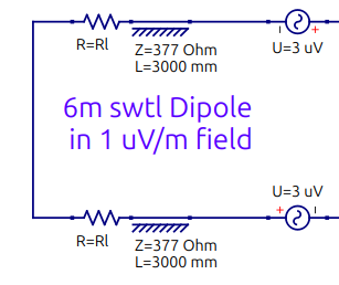
To characterize the entire SAS a combination of methods, modeling and measurement is used. Estimating the total SAS response is not straightforward. Both the probe nature of the antenna and use of SWTL model require special attention, theory and modeling. From A New Antenna Model a rather simple model for a dipole can be used to represent operation of a matched 6m dipole located in a 1 uV/m field. Radiation resistance is represented by ~3900 ohm resistance at each monopole tip, rotated by a 3m SWTL. This creates a good representation of the impedance for a dipole which is used to transfer power.
For a probe system, an even simpler model can be used. No current is present in the dipole so the voltage at the terminals can be considered to simply be it's length*field. These subsystem models can then be combined with a VNA measurement (at 50 ohms) of the rest of the SAS system which follows; connecting CAT5 cable and ShackBoard, to produce an overall antenna factor that provides a reasonably accurate measurement of the absolute field strength anywhere within the entire frequency range of the system.
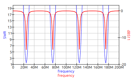
The following plot uses the SWTL model to show the return loss and SWR of a 6m dipole considered from a traditional matched perspective over a broad frequency range.
In the presence of a 1 uV/m external field, a 6m dipole is approximated by:
For reference, the theoretical model for the antenna
factor of an electrically short 6m dipole in a traditional matched
application at 5 MHz indicates a 7.55 dB gain from the incident field to a
high impedance voltmeter at the dipole terminals.
But Since the SAS antenna is operated as a probe, the 6m dipole is considered as a voltage source in series with the capacitive reactance of the dipole which is that of a 10.8 pF capacitor.
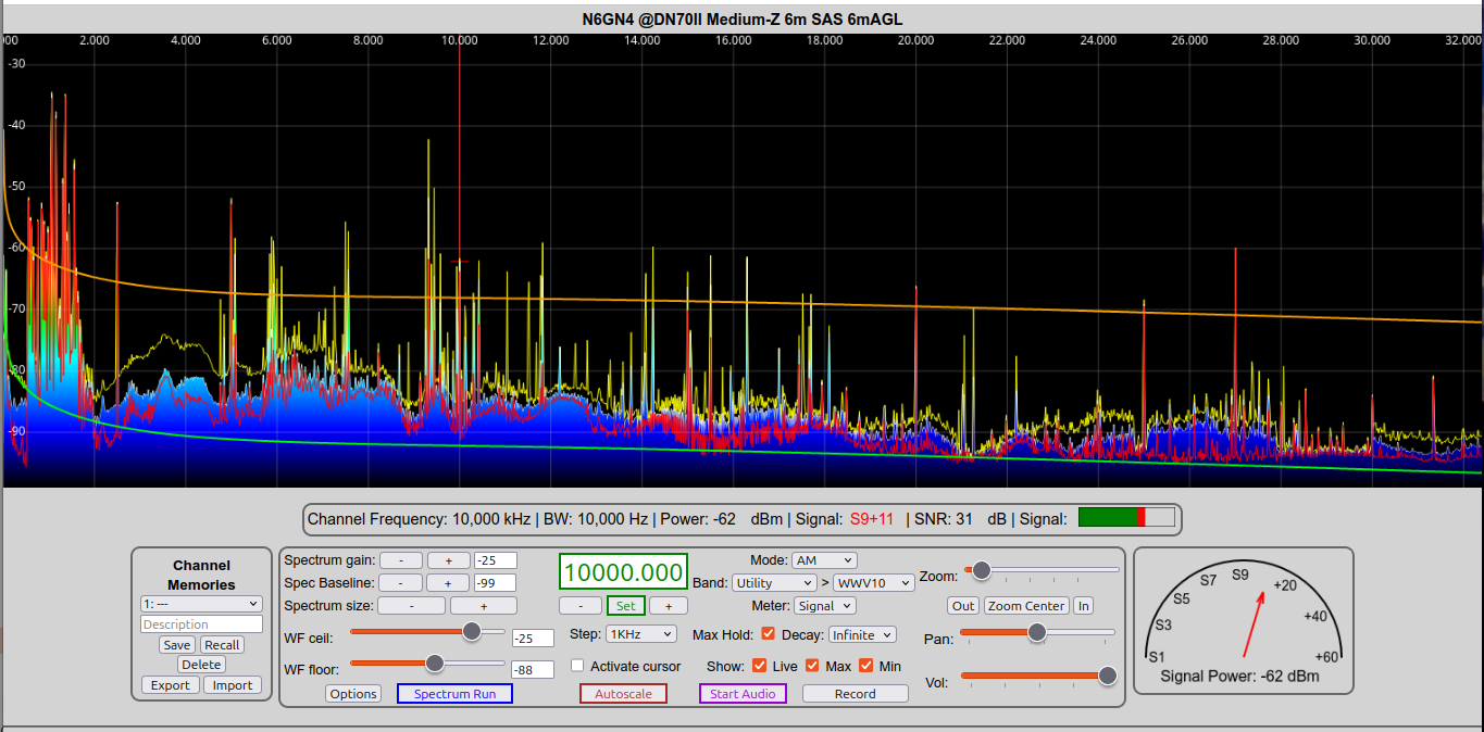
Using this model for the antenna a complete MediumZ Option SAS including feedline loss, ShackBoardv2 and combiner. may be partially measured and then modeled using QUCS to determine an antenna factor and thus the power produced in an ITU "Quiet Rural" or "City" zone. This can then be displayed as limit lines and shown along with minimum and maximum hold of live data:
:
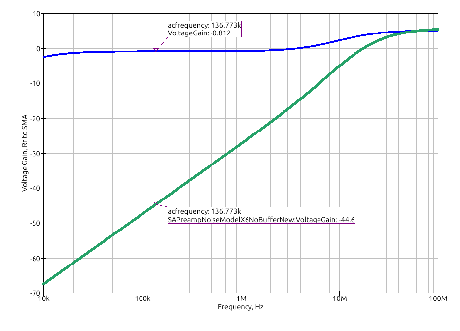
It should be recognized that the series capacitance of the dipole varies with dipole length so has modified the above response. This must be included in any antenna factor model. The circuits following the antenna and input filtering, including the SAPreamp, CAT5 connecting cable and ShackBoard taken together are measured to have approximately unity gain. For the HighZ option of the SAS this is modeled the red trace below:
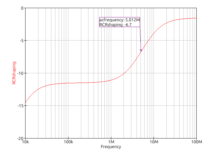
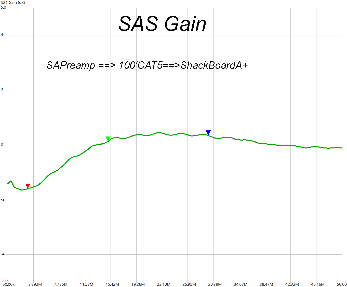
Measurement of this system, from the monopole terminals to the 50 ohm SDR input using 100 feet of CAT5 cable interconnecting the SAPreamp to the ShackBoard is shown below. This excludes the effects of additional frequency shaping that is produced by the mismatch between the dipole and shaping components. For the MediumZ option this produces a kind of 'shelving filter, beyond that produced the shaping components in the HighZ option.
This measurement was performed using a VNA calibrated to a 50 ohm reference impedance.As shown the gain from Preamp input to ShackBoard output of a HighZ option is approximately 0 dB from near DC to over 200 MHz.
The resulting overall Voltage Gains for HighZ and MediumZ options of the SAS are