ShackBoards

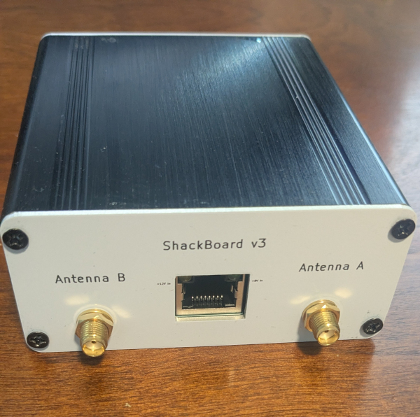
The ShackBoards are an active circuit for interfacing one of several types of antenna&preamp combinations to a station receiver.  It uses an ADA4930 ultralow noise driver to receive signals on either or both of two CAT5 transmission line pairs from an antenna unit and deliver them to receiving equipment while substantially maintaining the available signal-to-noise ratio over a very wide range of frequencies from VLF through VHF. It does this while also providing more rejection of unwanted common mode signals than can be obtained with passive circuits.  It does this while not introducing significant intermodulation or harmonic distortion even in the presence of high signal levels. This unit can also provides power and control for operating the remote preamplifiers.

There are presently two verstions; v2 and v3.  These are similar but v2 uses an external combiner to provide the 'performance mode' of operation while v3 has an active combiner added internally.  V2 may have slightly better IMD performance. Particularly in locales with very high FM BCB signals, distortion products may appear in the HF range. However v3 can provide continuous coverage from audio through VHF while v2 has a low end limited by the ferrite in the external combiner. v3 also provides both these combined outputs as well as balanced RJ45 output for use with future SDRs which are capable of fully balanced operation.  This operation offers better SNR, lower IMD and more resistance to unwanted common mode currents in a receiver system.

Features

  • Provides power and interface for all preamps; PreampA, PreampB & SAPreamp.
  • Very high CMRR
  • low distortion to transfer  SNR present at a preamp to a ham shack receiver
  • Receives one or two pairs of CAT5 RF from an associated preamplifier
  • Approximately 0 dB conversion gain(v2),  3dB gain (v3)
  • switches on the PCB to allows verifying low CMRR operation of  capable preamps
  • may also be used for initial testing of  Preamps, Junction Box and cables. 
  • Front Connections:
  • (v2) SMA: 2 pairs, one pair for each of A and B  CAT5 lines
  • (v3) SMA:  one combined output for each of A and B , RJ45 having differential A&B signals
  • Rear Connections:
  • 2.1mm barrel connector for power
  • RJ45 for CAT5 to preamp(s)), filter or line amplifier
  • External supply voltage 10-16 VDC, total current depends upon Preamp selection
  • Double-sided, 4-layer, silk-screen PCBs

  • (V2) Two configuration modes  are supported; Utility mode and Performance mode.

    Utility Mode

    • wide frequency coverage, 300 Hz to 300 MHz usable bandwidth
    • Dual outputs for each A and B CAT5 pair
    • -3 dB  gain for each output
    • typically -140 dBm (20nV/rt-Hz) noise floor

    Performance Mode  when used with external antiphase combiner

    • low noise, typically -154 dBm  (4nV/rt-Hz)  or lower noise floor
    • Single output from anti-phase combiner (required) for each A and B CAT5 pair
    • 0 dB conversion gain for each output
    • frequency coverage depends upon combiner, 10 kHz to 300 MHz typical

    (V3)  Internal combiner delivers .001 - 200 MHz coverage (in conjunction with HiZ SAS), without the need for an external combiner.

    • lowest noise, typically -160 dBm   or lower noise floor
    • Single output from internal combiner for each A and B CAT5 pair
    • Both A & B outputs from front panel RJ45 for balanced SDR use
    • 3 dB  gain for each output
    • frequency coverage 300Hz to 300 MHz typical


    Testing

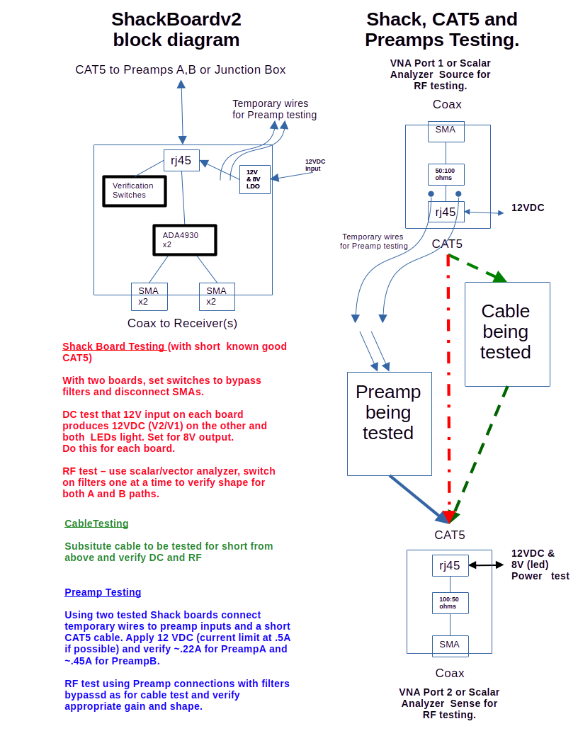
    Since assembled PCBs must be ordered with minimum quantity = 2 , this makes a good arrangement for testing. Using each of  two PCBs as a simple 50 Ohm <==> 100 balanced line adapter lets transmission through a length cable be measured.  Applying power to either of the interconnected boards also allows checking power function of each board.

    DC tests can be performed with a multimeter for power supplies. For RF testing a broadband measurement using a scalar or network analyzer is a very good method.  This may be done with a TinySA or nanoVNA. Loss through the system during a two-Shack board test should be near 0 dB. Typically CAT5 cable loss should be about 3 dB/30m at 30 MHz. This PCB may also be used for initial testing of  Preamps, Junction Box and cables. 
    There are also  switches on the PCB to allow verifying proper preamp performance.

    Since assembled PCBs must be ordered with minimum quantity = 2 , this makes a good arrangement for testing. Using each of  two PCBs as a simple 50 Ohm <==> 100 balanced line adapter lets transmission through a length cable be measured.  Applying power to either of the interconnected boards also allows checking power function of each board.

    DC tests can be performed with a multimeter for power supplies. For RF testing a broadband measurement using a scalar or network analyzer is a very good method.  This may be done with a TinySA or nanoVNA. Loss through the system during a two-Shack board test should be near 0 dB. Typically CAT5 cable loss should be about 3 dB/30m at 30 MHz.


    Use

    In addition to its main function of supplying power to Preamps and receiving differential RF over CAT5 cable and delivering the results to a receiver, this board also has a switch to disconnect the 12V supply from the input circuits of a probe preamplifier while leaving output stages operative.  This allows identifying common mode and other unwanted noise ingress apart from the intended balanced antenna. A better method is to simply short the dipole elements but this is not always possible or convenient so simply disabling the input high impedance OpAmps is useful to verify a system.


    V3 KiCad files, provide both source for schematic and layout as well as 'binary' for JLCPCB fabrication located within the 'Production' sub-directory.


    Material List

    What you will need to build this hardware


    Item Description

    Provider

    Source Code

    Notes

    Approximate Material Cost

    (excludes setup fees and shipping)

    Assembled ShackBoardv2 PCB

    Download ShackBoardv2 Kit Files

    ==> JLCPCB

    Download ShackBoardv2 Source Files

    ==> KiCad

     
    US$

    38x88x100mm Clam Shell Enclosure

    eBay


    Other sources possible. Enclosure needs to accept 84mm wide PCB. US$12

    38x88mm ShackBoardv2 Front Panel

    Download ShackBoardv2 Front Panel Kit Files

    ==> JLCPCB

    Download ShackBoardv2 Front Panel Source Files

    Select 'Aluminum" when ordering. These are panels only no components.
    US$1

    38x88mm ShackBoardv2 Rear Panel


    Download ShackBoardv2 Rear Panel Kit Files

    ==> JLCPCB

    Download ShackBoardv2 Rear Panel Source Files

    Select 'Aluminum" when ordering. These are panels only no components. US$1

    Donations gratefully received

     © 2025 n6gn