document.lastModified :

Field Probe Pre-amplifier

This project is for a small handheld portable field measuring device, particularly for locating, identifying and measuring noise levels in conjunction with a TinySA or (especially) a TinySA "Ultra" hand-held spectrum analyzer. It is intended to help identify and understand a particular candidate antenna site for amateur radio reception.

It is a member of a class of receive antenna systems using non-resonant and broadband antennas. Included in this are the Hybrid Antenna System which uses a similar PreampA electronics for the Loop-over-Earth and Beverage "Traveling Wave" antenna types as well as the Single Antenna receive system.

High Impedance Field Probe pre-amplifier Board.

Here's a portable arrangement using the TInySA "Ultra"portable spectrum analyzer with a 1m dipole

Assembly

Since there is no separate enclosure, once the assembled board arrives solder the 9V battery connector/pigtail to Battery +/- wire holes on the board. The only assembly required is to TyWrap a standard 9V battery to the back/bottom side and attach the two telescoping monopole antennas. The calibration curve will apply only to a specified total dipole length and vertical polarization when the board is held about 1m above the earth.

Test

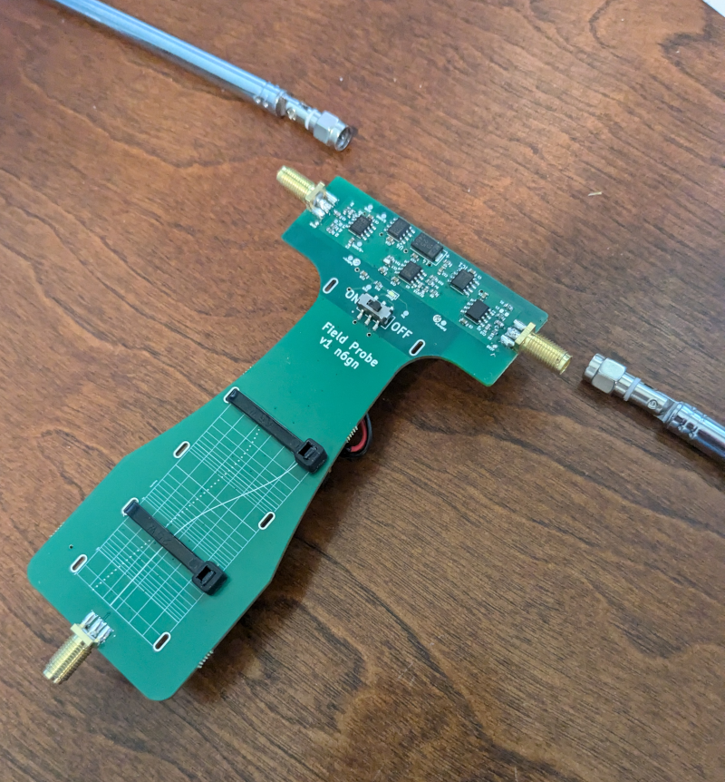
Verify that the test points marked, Vp measure as marked.

For better quick viewing of the design, download the Kit file from the Source Link below, unzip it and drop the .sch or .pcb file onto KiCanvas from a web browser. This should permit examination of the current schematic and PCB layout. As an alternative, install KiCad, download the FP Source file (an archive), open KiCad and select "Unarchive" from its File: menu. This should bring up the entire design, both schematic and PCB and allow viewing as well as modification.

Use

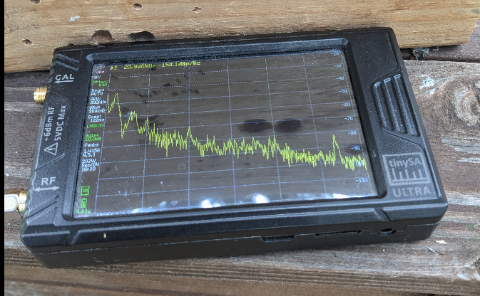
When used with the TinySA Ultra BW is set to 300 kHz for a 0-30 MHz span resulting in a 10*log10(3e5) = 55 dB offset such that kTB will display as -174 + 55 = -119 dBm. The TinySA can be set to display Marker noise power directly in dBm/Hz.

A starting point for settings might be:
  • 300 kHz RBW, 
  • LNA off, 
  • manual attenuation set to 0,
  • external gain set to 10 dB to adjust for the gain inside the FP

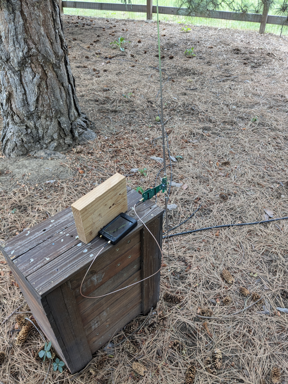
A first purpose of this probe is to identify areas for siting a permanent receive antenna system with regard to minimizing local noise sources. This involves surveying potential candidate mounting locations for minimum unwanted, often near-field, noise sources. To the degree that a user has any degree of freedom locations that appear better or worse may be identified. As a reference methodology, setting the telescoping monopoles to .5m each and holding the FP vertically polarized 2m above the earth seems a reasonable reference orientation.

Once a likely antenna site is selected on the basis of minimum noise within the sub-spectrum of interest between approximately 1 kHz and 200 MHz that site may be further examined by seeking to identify sensitivity of the noise level measured to polarization and azimuth. This may best be done by focusing on the signal-to-noise ratio (SNR) of a propagated signal, e.g. a NIST Time/Frequency standard station or other easily visible signal coming and changing the FP orientation to maximize SNR.

Because the FP has high axial ratio, because it predominantly linearly polarized along the axis of the monopoles, and because other sources of signal ingress have been eliminated by the high CMRR of the design, it is possible to get a high degree of nulling of a linearly polarized interferer which compromises the SNR of the desired signal. In this way, seeking to find a polarization and azimuth the optimizes not signal strength but SNR a better understanding of preferred orientation for a permanent installation may be discovered. This type of "noise nulling" can produce impressive improvements in SNR in situations where there is only a single interferer. In some situations this is many 10's of dB.

Sources of elliptically polarized interference may need to be mitigated with a more complex system such as the Polarimeter described elsewhere. If there are multiple interferers presenting similar magnitudes even though neither may be eliminated a best compromise for communications SNR may be found.


As a handheld tool it is very useful to examine SNR as polarization and azimuth are varied. The device has high axial ratio, that is, an incoming vertically polarized wave can easily be nulled by going to horizontal polarization.  Sometimes local and near-field noise results in highest SNR of DX signals occurring at neither of these polarizations, even recognizing that there is often significant decrease in levels due to earth absorption when oriented horizontally which also tends to push the arrival angle overhead.

For many uses, there is no need to know an antenna factor. Relative measurements of noise and SNR may accomplish all that is needed. For comparative measurement though it can be useful to know antenna factor. Antenna Factor for the Field probe in a 50 ohm environment with antenna set to 1m tip-tip and measured at 150 MHz calculated from a Jupyter Notebook created by Claude gives:

============================================================
MEASUREMENT SUMMARY
============================================================
                   Parameter         Value
                   Frequency     150.0 MHz
                  Wavelength       1.999 m
       Horizontal Separation         2.0 m
             Antenna Heights         2.0 m
          Direct Path Length       2.000 m
       Reflected Path Length       4.472 m
                Measured S21     -16.30 dB
              Electric Field 101.42 dBμV/m
            Received Voltage    90.18 dBμV
              Antenna Factor     11.24 dB/m
AF (theoretical, free space)    23.76 dB/m
============================================================
 as calculated HERE. It also provides general advice.

The value at every frequency may be obtained by examining the measured response from the input to the output and adding it.

Measured in a 50 ohm environment the frequency response is as shown below:
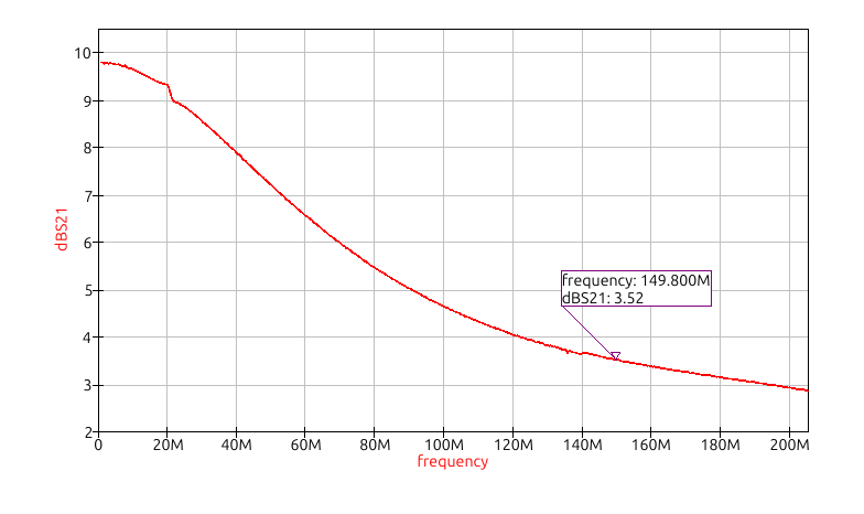
and shows a 3.5 dB gain at the 150 MHz calibration frequency.  The value at each frequency needs to be added to the Antenna Factor above.  Because the probe's preamplifier presents a very high impedance to the 1m antenna, there should be little mismatch adjustment required for the probe.

The same can not be said for the reference antenna.
When  questioned  about this:

"Is it not true that for the approach shown in Amplifier Gain Correction Guide it is necessary to maintain very good match to the reference antenna in order to know what the incident field is? Because the match far from resonance is so poor, mismatch error can be very difficult to measure. It may be that antenna modeling will be necessary to arrive at a correct AF?"

Claude says:

Antenna Factor Measurement - Limitations and Modeling Requirements

Antenna Factor Measurement: Limitations and Modeling Requirements

Critical Point: You are absolutely correct, and this is a critical limitation of the simple approach shown in the notebook. This goes to the heart of accurate antenna factor measurements.

The Problem with Broadband Measurements

At Resonance (150 MHz for your half-wave dipole):

  • Antenna impedance ≈ 73Ω
  • Mismatch to 50Ω is small (VSWR ≈ 1.46, ~0.2 dB mismatch loss)
  • The "negligible mismatch" assumption is reasonable

Far from Resonance:

  • Dipole impedance could be 200Ω, 500Ω, or even highly reactive
  • Huge mismatch loss (could be 10+ dB)
  • S21 measurement includes this mismatch loss
  • But the incident E field is the same!
  • The relationship between E and Vantenna is now governed by the antenna impedance and mismatch

Why the Current Approach Fails

The fundamental issue is that AF = E/Vantenna depends on:

  1. The antenna's effective length (which changes with frequency)
  2. The antenna impedance Zant(f) and its mismatch to Zsys
  3. The actual gain pattern (which changes off-resonance)

When you measure S21 far from resonance:

  • You get a low value because of poor mismatch
  • But you can't simply back out Vantenna without knowing the exact impedance
  • The transmit antenna also has frequency-dependent gain/impedance issues

The Proper Solution: Antenna Modeling

For accurate broadband AF(f), you need:

1. Electromagnetic Modeling (NEC, FEKO, CST, etc.):

  • Model your dipole geometry over ground
  • Get Zant(f) at each frequency
  • Get actual gain G(f) (not just 2.15 dBi assumption)
  • Get effective length Leff(f)

2. Calculate AF from First Principles:

AF(f) = (1 / Leff(f)) × √[(Zsys(1 + |Γ|²)) / (4 × Rrad(f) × (1 - |Γ|²))]

Where Γ = (Zant - Zsys)/(Zant + Zsys)

3. Or Use the Modeled Results

Use modeling to properly interpret your S21 measurements, accounting for all impedance and mismatch effects.

Alternative Approach: Three-Antenna Method

Another approach for broadband AF measurement:

  • Use three antennas and measure all combinations
  • Mathematically separate out individual antenna factors
  • Doesn't require knowing impedances explicitly
  • But still has practical challenges

For Your Specific Case (Active Probe)

Given that your probe has an internal high-impedance amplifier, you're actually in better shape than a passive probe:

  • The high-Z input minimizes loading of the antenna
  • The amplifier output is 50Ω matched
  • But you still need to know how the antenna characteristics (effective length, gain) change with frequency

Summary and Recommendations

Measurement Scenario Simple Approach Valid? Recommendation
Near resonance operation ✓ Yes Simple notebook approach is acceptable
Relative measurements ✓ Mostly Good for comparing similar antennas
System response characterization ✓ Yes Accept mismatch as part of system
Broadband absolute AF ✗ No EM modeling required
Far from resonance ✗ No EM modeling + impedance analysis

Bottom Line

You're right - for accurate broadband AF characterization, especially far from resonance, antenna modeling is necessary. The simple approach in the notebook is best suited for:

  • Near-resonance operation
  • Relative measurements
  • When you can accept the mismatch as part of the "system response"

For rigorous absolute AF measurements across a wide frequency range, electromagnetic modeling tools (like NEC, FEKO, or CST) combined with careful impedance characterization are the way forward.

Recommended Modeling Tools

  • NEC (Numerical Electromagnetics Code): Free, widely used for wire antennas
  • 4nec2: Free Windows GUI for NEC
  • FEKO: Commercial, comprehensive EM solver
  • CST Studio Suite: Commercial, full-wave 3D solver
  • HFSS: Commercial, industry-standard FEM solver

This analysis highlights the importance of understanding measurement limitations and the need for proper electromagnetic modeling when accurate broadband antenna factor characterization is required.


Material List

What you will need to build this hardware


Item Description

Provider

Source Code

Notes

Approximate Material Cost

(excludes setup fees and shipping)

Assembled FieldProbe PCB

Download Field Probe Kit 

==> JLCPCB

Download Field Probe Source 

pending better calibration curve, verify C2156927  TLE2426QDRG4Q1rail splitter selection
US$ ?

Telescoping Antenna (2)

Amazon


US$12

9V Battery&Connector, TyWrap (2)

Local HW supply


Mast Mounting Bracket

Download 25mm Mounting Bracket Kit

Download 31mm Mounting Bracket Kit

==> JLC3DP


N3AGE Designs.25mm is for the 23' & 32' masts.
31mm is for a larger mast.
Thanks Elmer!


Donations Gratefully Accepted © 2025 n6gn

 Back to HW Menu