0-2 GHz All-band, All-mode Transmit & Receive Converter
Converts any HF radio to any amateur band - 136 kHz through 1296
MHz better than 1 Hz frequency accuracy


Features
Simultaneously converts a 20 MHz
block from HF to and from anywhere in 0-2 GHz
2200m through 23 cm Amateur band
operation, converts LF through UHF
Fully coherent and fully synchronous
conversions
Full duplex - independent
conversions, simultaneous receive and transmit
~10 mW output for ~1 mW input on
transmit
Approximately 10/25 dB conversion
gain on receive, preamp off/on
Can be paired with an external
PA/preamp to produce higher power
Supports either GNSS or 10 MHz
discipline frequency reference
Typically better than .1 ppb,
<<1 Hz at 1296 MHz
WiFi web Interface, monitored and
controlled by way of a web browser
Configurable User Clock, may be used
to phase lock a user's HF radio or as shack frequency reference
Front Connections:
SMA: GPS Antenna or External 10 MHz
reference
0-2 GHz receive input
0-2 GHz transmit output
Rear Connections:
10-30 MHz Receive IF output
10-30 MHz Transmit IF input
Filtered, amplified and isolated GNSS
output for other devices
Selectable bypassed HF antenna Input
SMA:User Clock output 2 kHz to
160 MHz
2.1mm barrel connector for power
external supply voltage 7-32V @ approximately 5W
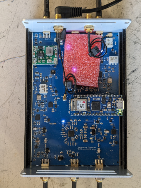
Double-sided, 4-layer, silk-screen PCBs
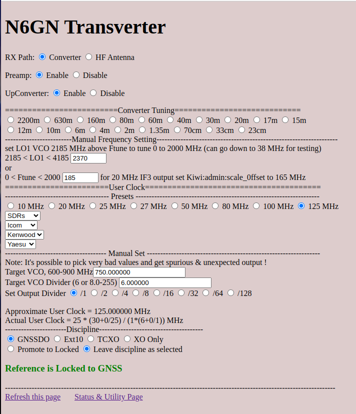
Web Interface
How It Works
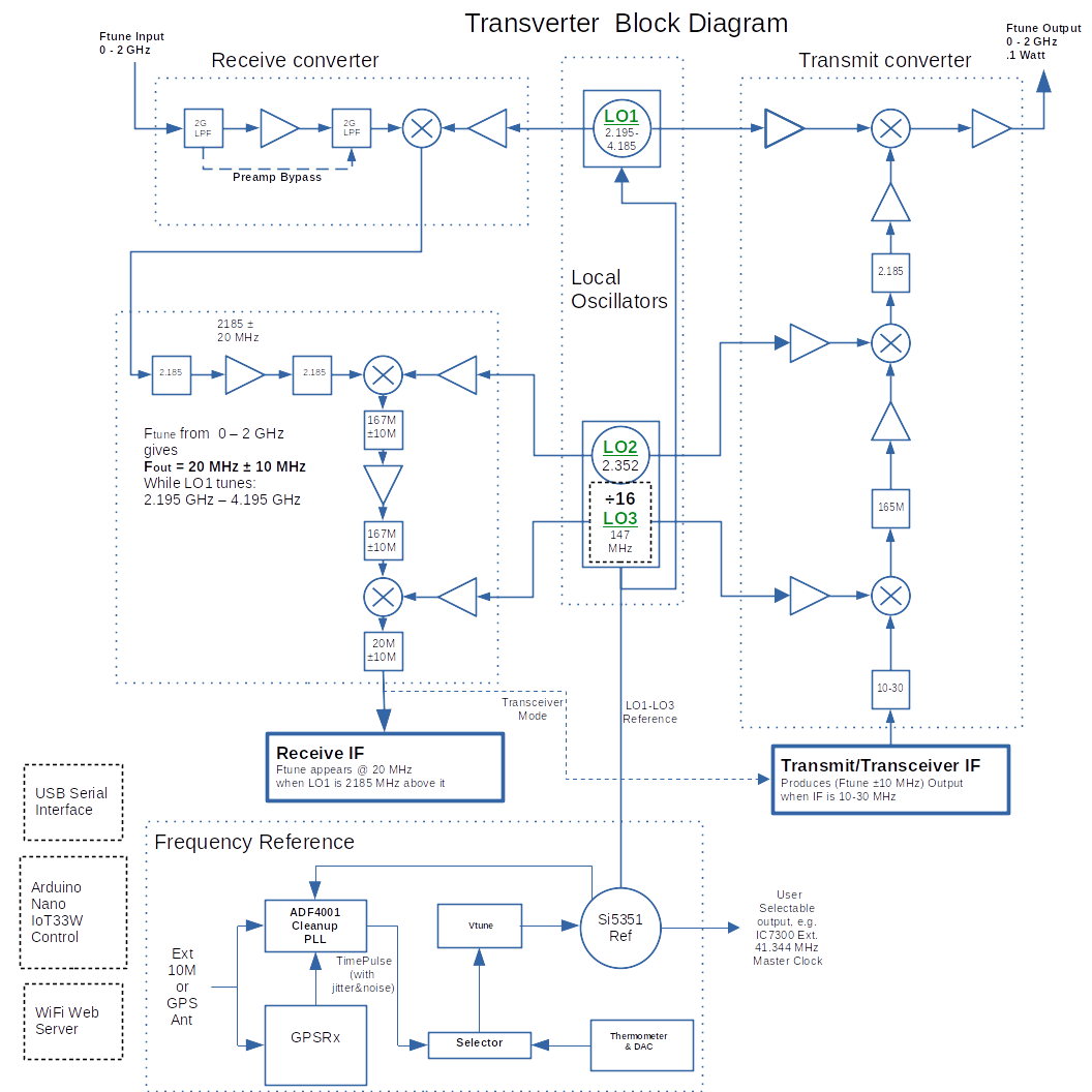
The block diagram above describes a frequency converter where a
range of frequencies is converted to another by an offset. This
is what usual amateur receive and transmit converters do. For example,
a 146 +- 2 MHz range of frequencies in the 2m band may be converted to
28 MHz in the 10m band for receiving on HF equipment. SImilarly a 2m
transmitting converter may convert a 28 MHz signal applied to a 146
MHz output on the 2m band. Complex modulation types are
maintained but simply offset to and from an HF band.
Simple conversion techniques involve an offsetting oscillator and
a mixer. For typical passive mixers, conversion is symmetrical
so it can be performed either lower frequency to higher or the other
way around. But the conversion/mixing process is nonlinear and
generates more than a single output. There are image frequency,
harmonic mixing and harmonics of the signal and of the local
oscillator (LO) present at the output. For simple systems filtering,
balance and other steps need to be taken to assure a single
frequency is converted without generation of unwanted signals.
This transverter uses a triple conversion technique to remove many
of the unwanted signals that are present in a simple conversion
process. It does this by generating an intermediate frequency which
is above the highest range of desired frequencies along with a
low pass filter to remove image frequency, LO and other unwanted
components. It offers the ability to quickly tune one of the
conversion LOs to produce a desired output over a wide range of
offsets.
For this transverter the goal is to convert the operation of an
amateur radio HF transceiver or transmitter/receiver combination to
and from any frequency from near-DC to 2 GHz. The triple conversion
method shown along with a disciplined LO system which is common to
both transmit and receive conversion is used to generate accurate
copies of an incoming/receive signal to an HF intermediate frequency
(IF) between 10-30 MHz while a symmetrical process is used to
simultaneously convert an HF transmitting IF to the same range.
The following plot is a vector network analyzer (VNA) measurement
of the transmit side of the transverter in action. Because without
extra effort the VNA cannot measure frequency converted signals,
that is, the stimulus and sensed signal must be at the same
frequency as the detected signal within the VNA, to make this
measurement the transverter was tuned to produce no net frequency
conversion; the offsetting frequency was set to zero. With this
done, both the receive and transmit conversion paths can be
measured. The measurement was taken with 30 dB of extra
attenuation and shows the transmit converter flatness
and about 14 dB of conversion gain where the output power was about
+13 dBm or 20 mW.

Phase noise performance of the three LO's give a good approximation of
end performance. All LO's are referenced to the same clock
so within their PLL bandwidth of ~ 60 kHz have cancellation. The
lower and upper plots give an idea of VHF, -105 dBm/Hz and
2 GHz, -85 dBm/Hz performance near the carrier, respectively:
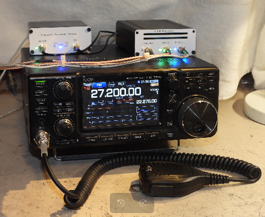
Transverter in use to convert an Icom IC7300 for use on 70cm NBFM. A
Transceiver Interface conditions the Icom input/output
for use with the transverter and is powered from the Aux
Connector. The User output from the Transverter is set to 41.344
MHz
and provides GNSSDO master clocking for the IC7300. This produces
sub-ppb precision to the 0-2 GHz input and outputs from the
Transverter.
In this short video clip video clip a TRXduo HFSDR is used
directly with the Transverter while controlled by Thetis from HPSDR
to create an all band, all mode, disciplined amateur station.
The IC7300 Transverter system above is transmitting USB on
1296.100000 MHz.
These are entirely separate systems actually on-air, each with
its own biconical antenna separated about 25 meters.
Although the TRX is fully capable of external disciplined
clocking so fully phaselocked by its TRansverter, in this particular
recording
it is operating from its internal clock so may be off frequency
a few Hz.
Here is a KiwiSDR receiving a broad spectrum showing VHF
HDTV Channel 9 OTA from 100 km distant.
Notice the pilot carrier nominally at 186.309440559 MHz which
measure within 5 milli-Hz of that after an hour's sample with
fldigi.