Appendix 1
Toroidal Transformer Construction
This appendix describes a practical method to fabricate suitable toroidal core transformers for use when measuring high impedance balanced transmission lines. Most of these are flux-coupled ‘voltage transformers’ with windings around a toroidal ferrite or carbonyl core. Some care is taken to provide as great a useful frequency range as possible, centered on a target frequency.
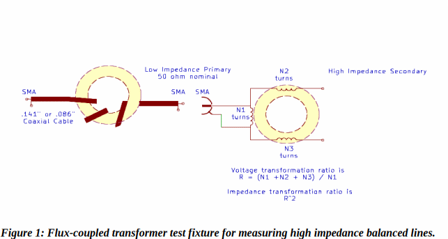
The toroidal transformer test fixture used for these experiments generally is as shown in Figure 1. Two cores are used, one wound with flexible silicone dielectric wire for voltage transformation and the other with a length of semirigid 50 ohm coaxial cable to provide additional balance and reduce common-mode coupling.
For each of these, liberal use of plastic ties is made in order to maintain as much stability as possible. Because at high impedance, stray capacitance is more of a problem than stray inductance it is important that during use conditions remain the same, particularly between calibration and measurement with a VNA.
Wide band high-ratio transformation by a flux-coupled transformer can become difficult. Whether the transformer is used in a voltage step-up or step-down application, the design is caught between two extremes. On the low frequency end enough inductance must be achieved in each winding such that it is significantly higher than the connected impedance to be transformed. On the high frequency end, inter-turn and inter-winding capacitance creates a resonant circuit with a winding’s inductance such that effective transformation ceases. This is particularly a problem when used in fixturing of error-corrected (calibrated) VNA measurements because small changes in capacitance, even those due to small changes in connection lead dress, can tune the resonance and destroy the corrected accuracy of a measurement near the resonance.
Table 1: Construction detail for various core types showing transformation ratios and useful frequency range for >10 dB return loss.
|
N1 Turns/ (length”) |
N2 Turns (length”) |
N3 Turns (length”) |
Voltage ratio |
Secondary Z (50 ohm in) |
Core Type diameter-mix |
SWR < 2 Range MHz |
Notes |
|
3 |
- |
- |
1 |
50 ohms |
FT240-43 |
N/A |
.141” coax |
|
1 |
2 |
- |
1-2 |
*50-450 |
BN-43-7051 |
*3-200 MHz |
Binocular core high μ ferrite |
|
2 |
3 |
- |
1.5 |
112 |
BN-43-7051 |
.5-35 MHz |
Binocular core high μ ferrite |
|
4 (7.1”) |
2 (3.4”) |
2 (3.4”) |
2 |
200 ohms |
T130-6 yellow/clear Carbonyl SF |
110-500 MHz |
|
|
4 (9.1”) |
2 (6.5”) |
2 (6.5”) |
2 |
200 ohms |
T200-6 yellow/clear Carbonyl SF |
110-220 MHz |
0.2 dB IL |
|
4 (7.1”) |
3 (7.1”) |
3 (7.1”) |
2.5 |
313 ohms |
T130-17 blue/yellow Carbonyl |
110-170 MHz |
|
|
3 (5.1”) |
3 (6.8”) |
3 (6.8”) |
3 |
450 ohms |
T130-6 yellow/clear Carbonyl SF |
60-210 MHz |
|
|
1 (4”) |
3 (11”) |
- |
3 |
450 ohms |
BN-43-7051 |
3-165 MHz |
Pri AWG#18 Sec AWG #22 |
|
4 (7.1”) |
5 ( ”) |
5 ( ”) |
3.5 |
613 ohms |
T130-17 blue/yellow Carbonyl |
75-160 MHz |
|
|
1 (4”) |
3.5 (11”) |
- |
3.5 |
613 ohms |
BN-43-7051 |
2-130 MHz |
Pri AWG#18 Sec AWG #22 |
|
3 (5.6”) |
4 (7.4”) |
4 (7.4”) |
3.67 |
682 ohms |
T100-17 blue/yellow Carbonyl |
|
|
|
3 (5.6”) |
4 (7.4”) |
4 (7.4”) |
3.67 |
682 ohms |
T100-6 yellow/clear Carbonyl SF |
65-165 MHz |
|
|
3 (5.6”) |
4 (7.4”) |
4 (7.4”) |
3.67 |
682 ohms |
T130-17 blue/yellow Carbonyl |
110-210 MHz |
|
|
5 (11.5”) |
7 (16.4”) |
7 (16.4”) |
3.8 |
722 ohms |
T200-6 yellow/clear Carbonyl SF |
30-75 MHz |
|
|
6 |
8 |
9 |
3.83 |
734 ohms |
T200-2 red/clear Carbonyl E |
25-55 MHz |
|
| |
|
|
|
|
|
|
|
|
*approximate, depends upon application |
|
|
|||||
Voltage Transformers
For the wire windings, as shown in Table 1 an overall length of wire is used with the length for the primary marked on the center of the span. Wire strippers are then used to open gaps in the insulation so that the stranded wire inside can be well tinned with a soldering iron. The length is passed through the core and a plastic tie used to position one of these tinned locations after which the central length is wound so that it encompasses the entire core, leaving the second opening positioned and tied down adjacent to the first and prepared for connection to an PCB SMA connector. In this way the primary utilizes the entire toroidal core. The remaining lengths of the conductor create the secondaries. They are wound continuing in the same direction as the primary so that they each utilize about half of the remaining core and exits opposite the primary connections. Inter-turn spacing is made closer for the portions of the secondary which are near the primary and wider spaced near their exit at the highest impedance point. This helps reduce inter-turn capacitance and can raise the self-resonate frequency of the transformer somewhat. For all windings, plastic ties are liberally used to secure turns into position.
Although not shown in these examples, the self-resonant frequency of these transformers can be increased by using smaller gauge wire for the secondary windings. This reduces inter-turn and inter-winding capacitance which resonates with the transformer’s inductance and determines the frequency of the resonance. Using small gauge magnet wire, #28 AWG for example, can extend the useful frequency range of these transformers when used as part of a high impedance measurement.
The PCB mount SMA connector has all but one of it’s shield connections snipped leaving two connection points available. These are soldered to the previously tinned primary connections. This arrangement results in minimal stray inductance for the primary connections. This same process is used for each transformation ratio.
After fabrication, a test fixture can be examined and qualified for use by 1-port measurement. Since the goal of the fixture is to adapt to a measurement context different from 50 ohms, ideally at a ratio equal to the square of its turns ratio, a measurement of a quality resistor near the target impedance can give an indication of the useful frequency range of the fixture. Figure shows a VNA measurement of a X:Y turns ratio fixture measured from a 50 ohm calibration. Return loss becomes a useful measure of the overall fixture’s ability to meet the requirements. In Table 1 provides estimates for a variety of transformer designs.
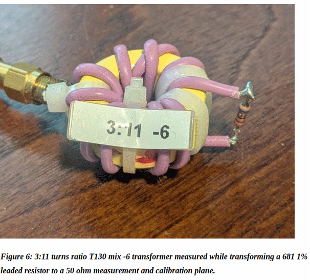
Figure 2 shows the return loss of a 3:11 T130 mix -6 transformer shown in Figure 6 measured from 1-500 MHz while a 681 ohm 1% leaded resistor is connected to its secondary. Return loss is greater than 10 dB, SWR < 2:1, only over a useful range of 66-167 MHz where it is being considered for use as a test fixture.
This measurement technique is not only useful for qualifying useful range but also for learning sensitivities and best fabrication practices.
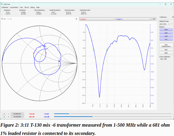
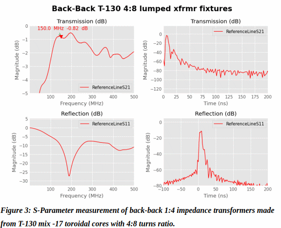
Figure 3 shows an S-Parameter measurement of back-back 4:8 turns ratio transformers measured from a 50 ohm calibration environment.
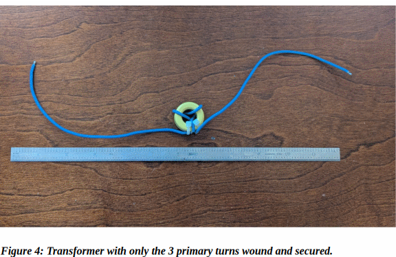
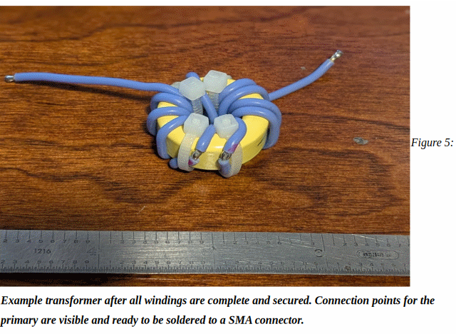
An example of a transformer with only a prepared 3-turn primary wound is shown in Figure 4.
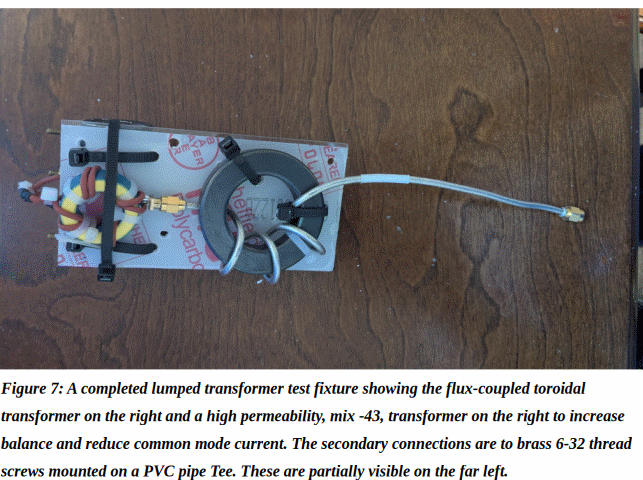
Balance Transformer
The transformer used for the balun uses a semi-rigid coaxial cable, secured and wrapped in a similar way to a secondary of the flux-coupled transformers so that the cable exits on opposite sides of the core. On the side which will be connected to the flux-coupled transformers primary SMA, the excess cable length is kept short so that after connecting to the SMA connector on the other transformer there will be as little separation between toroid as possible.
It should be understood that even with this construction technique, the resulting balanced, transforming test fixture is not perfect since compared to the very high impedance of the LUT it isn’t possible to completely eliminate common mode current through it.
A completed fixture is shown in Figure 7.
Material List
Toroids, Micro-metals KitsandParts
Stranded Silicone Insulated Wire Amazon