Experiment 10
This Experiment is measurement of a 64‘ length of hybrid transmission line made using AWG#28 wire. Port 1 is fixtured using one of the original surface wave transmission line launchers previously described.
40 feet from that launcher the single wire is split into two conductors which diverge over the next 16 feet to become 1 meter separated balanced transmission line.
After the split these line continue to 72’ where they are received by the Klopfenstein tapered transmission line fixture used in previous experiments.
One measurement shows the result with equal conductor lengths in the balanced line region while another shows the results when 1m of additional length is added.
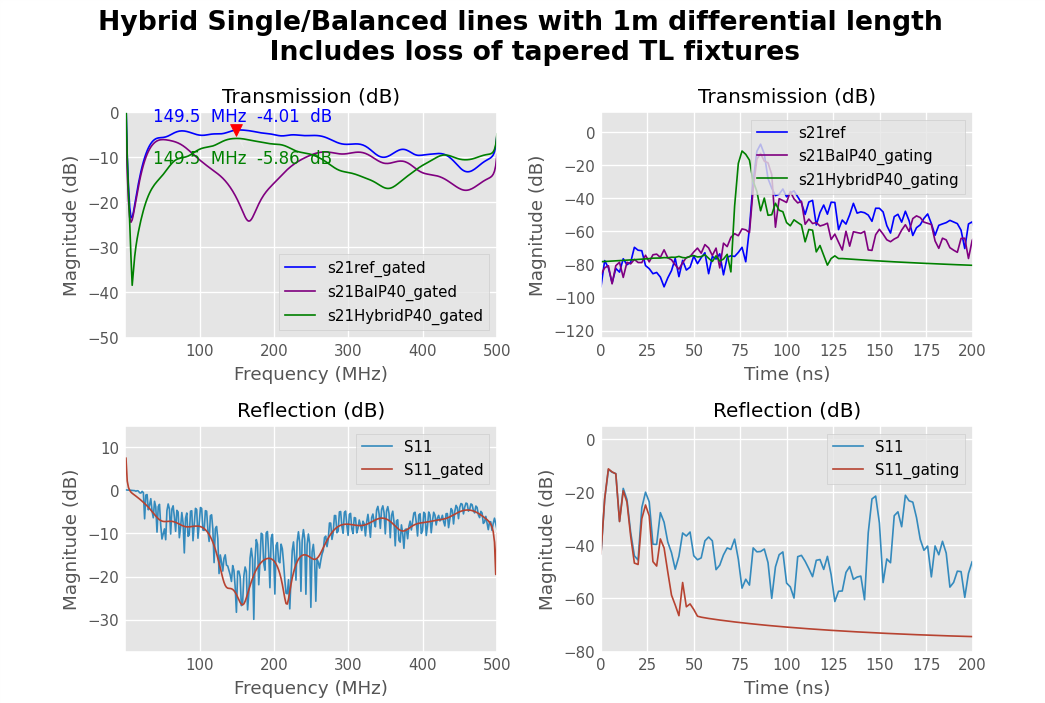
The blue data trace, S21ref_gated, shows the results from the Experiment 9 where there is a single conductor with identical SWTL tapered transmission line fixtures at each end.
The maroon trace S21BalP40, shows S21 with the single wire split two-ways and received at Port2 with a 1m spaced Klopfenstein tapered transmission line transformer.
The green trace, S21HybridP40, and shown in Figure 1 shows the result after 1 meter of additional length was inserted into one of the balanced line conductors.
Calibration at the input to the SWTL fixture and Port 2 is in 50 ohms. When not a second SWTL fixture, the test fixture at the Port2 end was a 1:2 turns ratio mix -41 binocular core transformer. Fixture losses are not included in calibration so are included in these measurements.
Comparing these results with measured attenuation for the lumped transformer fixtures measuring attenuation of similar balanced line in Experiment 1 below 1 dB and the results of Experiments 5,6 and 7 showing combined line and fixture losses on the order of 3 to 4 dB, considering the principle of conservation of energy it is evident that no significant extra attenuation is caused due to radiation from either the single conductor or balanced line portions of this experiment.