Experiment 12
Sample Experiment
[A snapshot of this page from February 2026 along with directories containing tools and programs to use is available in compressed form for those who want to use them as a starting point for further investigation. This includes Jupyter notebook, 3DPrinting, and VNA files.]
This experiment creates SOLT or TRL calibrated measurements of one pair from a length of CAT5 UTP cable.
This experiment is provided as a first step in configuring hardware and software tools to perform a calibrated measurement of a transmission line.
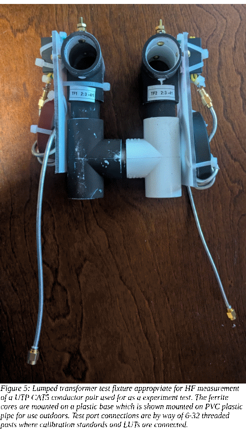
The test fixture hardware can be a lumped transformer test fixtures as described in Appendix 1. If future experiments are likely to be at HF then the BN-43-7051 with a 2:3 turns ratio could be a good choice. If VHF measurements are anticipated then a carbonyl toroid chose from Table 1 might be used.
A nanoVNA V2 Plus4 or similar VNA compatible with the nanoVNA-qt software previously installed.
The VNA is connected to the test fixtures with a 50 ohm cable. It would also be connected to a host computer, conveniently a laptop to make the entire arrangement portable.
Calibration using SOLT calibration standards consisting of Standards:
short - short wire connecting the two test ports
open – no test port connection
load – 100 ohm leaded resistor with short leads across the test port connections
thru – short jumpers between the Port1 and Port2 test fixture connections.
are made after setting up the VNA to sweep a suitable range.
A short section of a single pair from a UTP CAT5 cable makes a suitable LUT.
For a TRL calibration only
thru – short jumpers between the Port1 and Port2 test fixture connections.
open – no test port connection
Line – the LUT to be measured
are necessary.
On the hosting computer first
install Python
configure a virtual environment
install and activate Jupyter Notebook
as described in Appendix 4.
Additionally acquire and unzip the directory for this Experiment within the virtual environment project directory. Use Jupyter Notebook to open the notebook within that directory.
Run the notebook and verify that sample data is acquired and plotted from the sample data directory.
Calibration & Measurement
This is a starting point for Transmission Line Experiments. SOLT calibration is native to the nanoVNA-qt program to provide error correction and data measurement. It is able to produce Touchstone format S-Parameter data files. Generally two test fixtures are attached to the VNA by test cables. Together they serve to adapt the VNA’s environment, often 50 ohm coaxial connection, to that of a DUT or LUT of interest.
Two calibration methods, (S)hort, (O)pen, (L)oad and (T)hru or SOLT and (T)hru, (R)eflect), (L)ine or TRL, can be performed to provide input to the Jupyter notebook for analysis and presentation. These two methods can have the Thru and either an Open or Short used as a (R)eflect standards in common.
For this sample experiment, either or both of these methods may be used since both enable the same kind of analysis of a LUT. The TRL method may safely be omitted and be left for the advanced experiment who is interested.
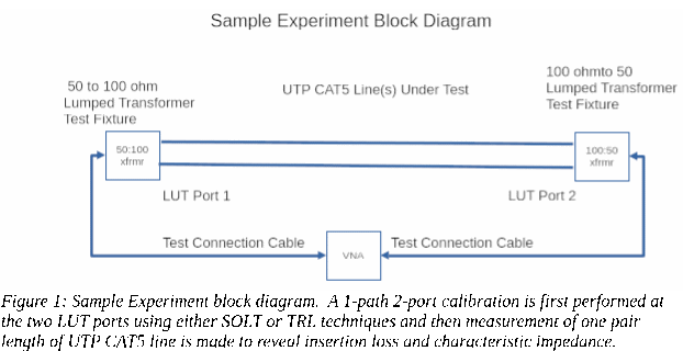
Experiment Test Fixture
The experimenter will need to provide 50 ohm test cables long enough to attach to test fixtures located on each end of a LUT. The cables may be of any good quality coaxial cable such as LMR-240 with SMA connectors on each end.
A test fixture made using mix -41 binocular core BN-43-7051 having a 2 turn primary and 3 turn secondary makes a reasonable choice over the 1-30 MHz frequency range.
Experiment LUTs
For this example, three sample LUTs can be prepared. To do this, cut 146" of inexpensive CAT5 UTP cable and use an electric drill to untwist and separate the pairs while being careful not to change the twist of each pair. Leave one of these four pairs at full length for the (electrical length) 5m test cable. Cut another pair to 58.4" to use as the 2m test cable and the a remaining pair to 29.2" to use as the 1m test cable.
In this example a nanoVNA-v2-plus4 is used with nanoVNA-qt which with a NULL calibration file to sets the frequency range from 3 MHz to 125 MHz and with 512 frequency steps. It is a NULL file in that while nanoVNA-qt sees it as a requisite .cal file, it doesn’t actually modify the raw measured data. The selected sweep range is from a frequency where the longest 5m line is about 20 degrees long up to an upper frequency where the shortest 1m cable is about 150 degrees long. This range is selected to permit TRL calibration methods to be used if the experimenter desires. A large number of points are used to cover various analysis scenarios.
Calibration & Measurement - SOLT Method
From nanoVNA-qt load TRL-1m-2m-5m-512pointNull.cal
This sets up the nanoVNA to calibrates with SOLT. If after measuring each calibration standard the RAW data can also be saved for use with the TRL calibration later. At Port1 measure calibration standards. At least at first, a leaded resistor of nearly the same value as the test fixtures, an open, a short and a through connection is all that is required. Generally use these with short leads. If the binocular core is used for a picture, a 100 or 110 ohm resistor should be fine.
These steps may be bypassed if only SOLT calibration methods are anticipated.
• RAW-1m-2m-5m-512point-open.s1p
• RAW-1m-2m-5m-512point-short.s1p
• RAW-1m-2m-5m-512point-110ohmload.s1p
• RAW-1m-2m-5m-512point-thru.s2p
DO NOT APPLY these measurements in the SOL(T) calibration window yet. That will be done after TRL measurements are completed in the next step. Thus these are all “raw” measurements including VNA errors as well as test cable and test fixture characteristics. Calibration mathematically removes their effects and returns corrected results.
The 1m, 2m and 5m can be measured for TRL use, first with their Port2 end left disconnected rather than connected to its test fixture to give:
• RAW-1m-UTPCAT5-open.s1p
• RAW-2m-UTPCAT5-open.s1p
• RAW-5m-UTPCAT5-open.s1p
and again, but connected to test fixture Port2, to measure them as 2-port transmission lines:
• RAW-1m-UTPCAT5-thru.s2p
• RAW-2m-UTPCAT5-thru.s2p
• RAW-5m-UTPCAT5-thru.s2p
Once the SOLT calibration data has been collected, it can be applied within nanoVNA-qt to create the error adapter values used to produce error corrected data from the viewpoint of the Test ports. Simply press “Apply” in the nanoVNA-qt calibration window to accomplish this.
The lines can be re-measured with their Port2 end left disconnected rather than connected to its test fixture to give SOLT corrected data:
• SOLT-1m-UTPCAT5-open-corrected.s1p
• SOLT-2m-UTPCAT5-open-corrected..s1p
• SOLT-5m-UTPCAT5-open.-corrected.s1p
and again, but connected to Port2, to measure them as 2-port devices. Results are saved for
• SOLT-1m-UTPCAT5-thru-corrected..s2p
• SOLT-2m-UTPCAT5-thru-corrected..s2p
• SOLT-5m-UTPCAT5-thru-corrected..s2p
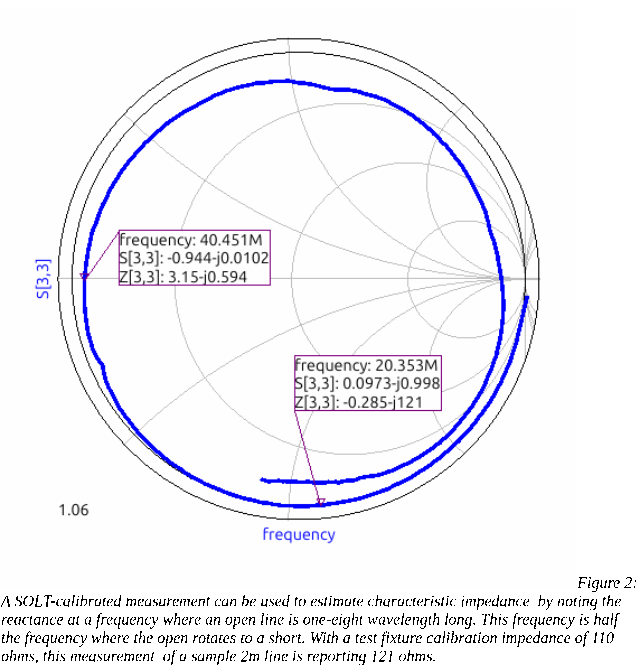
Line Impedance Estimate Using SOLT-Measured Data
The SOLT xxx-open.s1p measurements can also be used to estimate line impedance using a different technique. By measuring the series reactance at one-half the frequency where the line's length becomes a quarter wavelength – the frequency where an open line measurement rotates the measured value to a short. At half this frequency the line is one-eighth wavelength long. The reactance measured at that frequency is an estimate of the line's impedance. This estimate can be compared with the result obtained from the TRLcalibration utility. Figure 2 shows an example of this kind of estimation. Note that although in a normal CAT5 cable group of four pairs, each pair may have a characteristic impedance close to 100 ohms, taken by itself without shunt capacitance to the other pairs and if present, a shield as well, the impedance must be higher.Calibration & Measurement - TRL
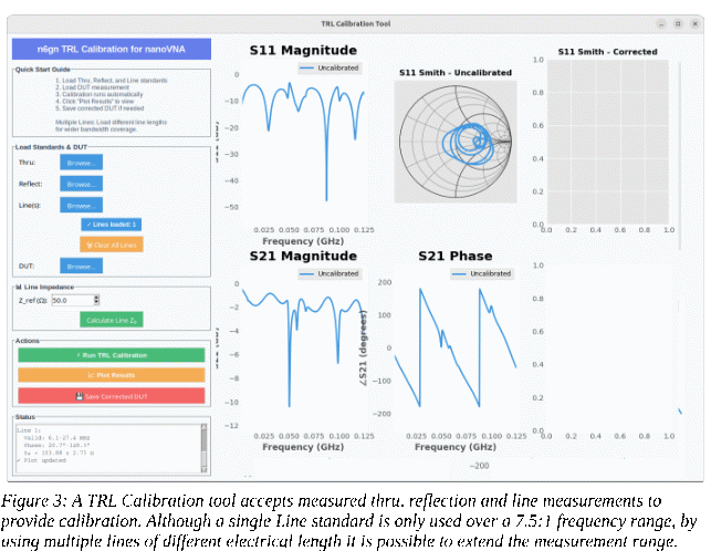
For the TRL method the TRLcalibration program in the second Jupyter cell can be run and the these data used to estimate the impedance of each of the three lines and also generate S-parameter files for them. This program can also be run stand-alone directly from python3 outside of the Jupyter Notebook.
When the TRL Calibration Tool application is run a window will pop up. The previously measured but uncorrected standards; Thru, Reflect(open) and Line(s), from above are used by the application to produce and plot TRL-corrected DUT data which can also be saved as .s2p as it for a SOLT calibration. The same lines used for TRL calibration can be entered as DUTs and one-at-a-time, be plotted and have their data saved as
• TRL-1m-UTPCAT5.s2p
• TRL-2m-UTPCAT5.s2p
• TRL-5m-UTPCAT5.s2p
so that the SOLT-calibrated and TRL-calibrated line measurements may be compared.
Additionally, the line characteristic impedance estimator can be run from the application to provide a measure of each line’s characteristic impedance.
Calibrate and measure your own LUT:
Measure the calibration standards to calibrate the VNA using one of the the two methods. If you chose a SOLT calibration, use nanoVNA-qt to save the results
If you chose a TRL calibration, use nanoVNA-qt to save the results for the T, R and L standards, where the (L)ength standard is your LUT.
Use these files with the TRLcalibration cell to generate a line impedance estimate and using the Line data as DUT, plot the results from the window generated by the calibration cell in notebook.
Modify the file used at the beginning of the code section of a cell to point at your newly measured .s2p data for the LUT.
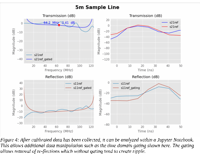
Modify the time gate parameters according to the approximate electrical length of your LUT where length-in-ns is approximately the same as electrical length-in-feet . If measuring UTP CAT5 then a velocity factor, Vr = .7, can be used to estimate electrical length from physical length.
Put the cursor into the code section of display cell and RUN (shift-enter or from the menu) to get your device displayed.