External PLL for GPS frequency reference of VHF WSPR Transceivers and Transverters
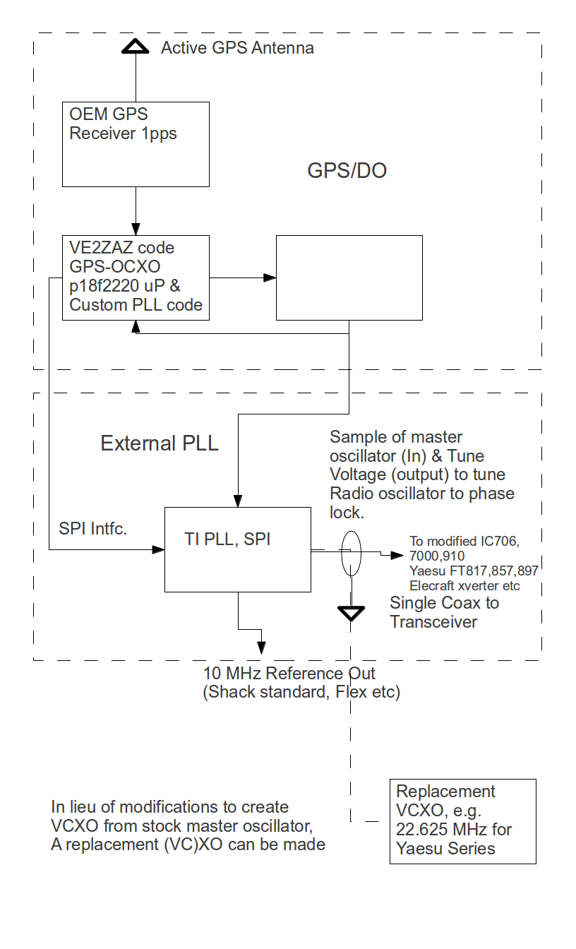
The external Pll project block diagram is as shown below.
An OEM, single board GPS receiver (RoyalTek REB21R) is used with an external active antenna to provide one pulse/second GPS timing as in input to a PIC processor running VE2ZAZ GPS/DO code. The PIC counts the frequency of the local OCXO, compares it to the 1 PPS signal and steers (disciplines) the OCXO to be the same frequency. This digital PLL has configurable sample size, loop bandwidth, holdover and a host of other features that can be accessed with a stand-alone Windows executable that manages it all.
Once the GPS receiver has acquired satellites and is providing the 1 PPS signal, the PIC steers the OCXO to the correct frequency. For the OCXO we are presently using, it appears that significantly better than 1 ppb accuracy is achievable.
In addition to this GPS/DO, the PIC also configures the TI CDCM7005 such that an external VCXO, ranging from low- MHz to 3000 MHz, can be phase locked to the 10 MHz OCXO signal. This is accomplished with 16 bit M/N integer dividers so that the VCXO is coherent and a rational multiple of 10 MHz. The PLL loop parameters as well as several derivative outputs of the VCXO are configurable. This allows not only phase locking the external VCXO but also providing additional 10 MHz or other frequency output for additional uses such as shack frequency standard or SDR external frequency reference. If the PLL is locking, say, an Elecraft 2 m transverter LO to 116.000000 MHz this second output might be used as the 10 MHz reference for a Flex SDR which is used as the WSPR IF. This is essentially the configuration anticipated for use at KP4MD.
The main locked output has two signals on it. One is a sample of the transceiver or transverter master oscillator that is being compared to the 10 MHz reference. The other is a VCXO DC tuning voltage that will steer that same oscillator to be phase coherent with the 10 MHz reference. Thus, on a Yaesu FT857, a tap of the master oscillator signal at low level, -20 dBm comes into the external PLL and a DC voltage produced by the PLL rides on the same coax going back to the Yaesu transceiver. The master oscillator of the transceiver must be modified in order to create a VCXO out of it. This VCXO only needs enough tuning range to be able to correct the time & temperature variations of the particular oscillator.
I'm hoping that I may be able to construct a no-solder method of both coupling to the master oscillator and also steering it's frequency. I'm anticipating using a single turn loop with a varicap that tunes the loop a considerable distance away from the oscillator frequency. By varying the capacitance it is possible to “loop modulate” the master oscillator at the same time a bit of the RF is being sensed and provided back to the external PLL. This circuit has not yet been constructed and the breadboard external PLLs made to date have only been applied to the Icom 706 series which already have a tuning potentiometer for trimming the master oscillator frequency. This is the technique currently being used on 2 m and 432 WSPR at N6GN. Here's a picture of the prototype external PLL with some labels.
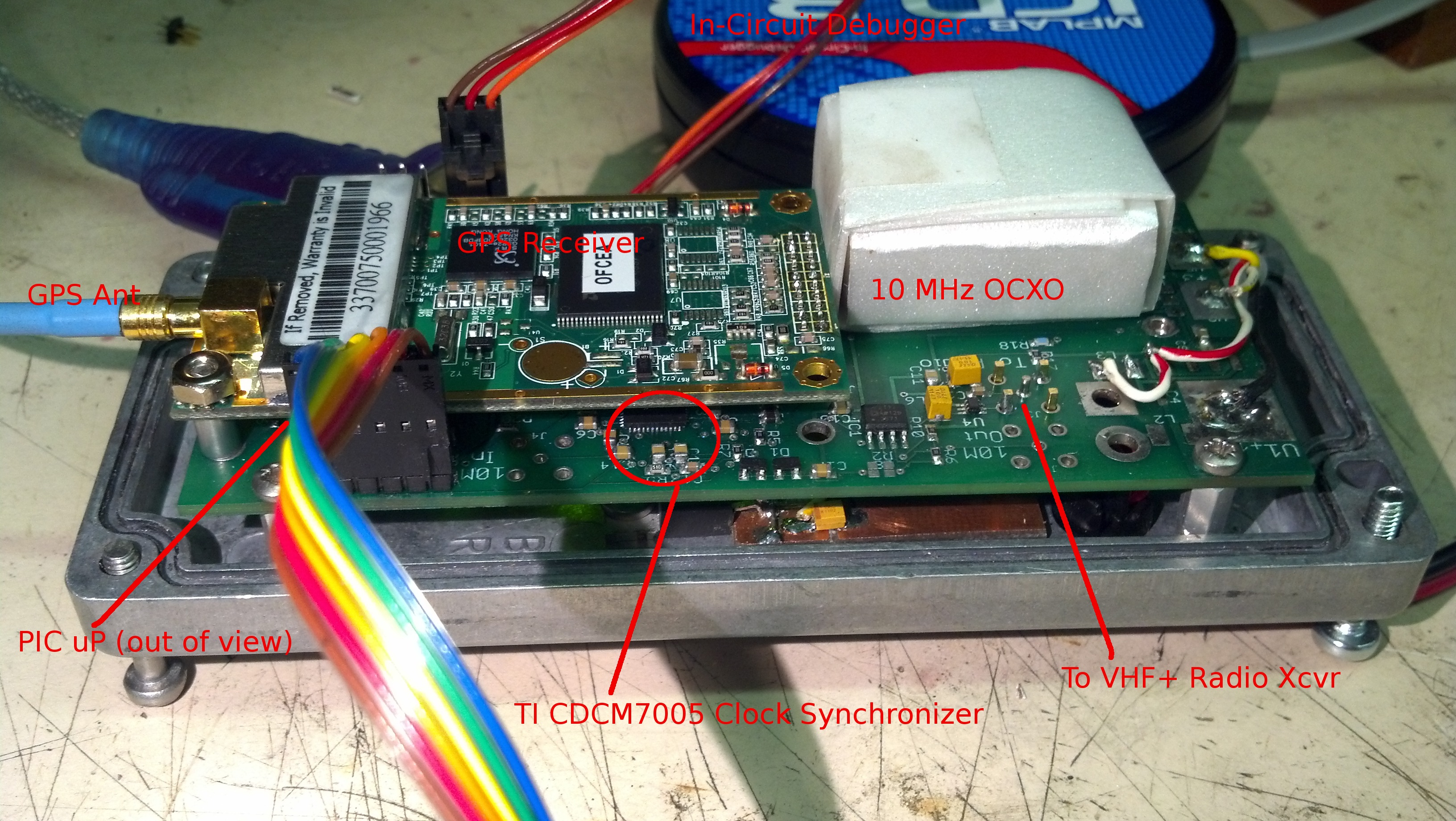
The PIC code to configure the TI PLL chip has not yet been written but the prototype can be seen in the photo with both in-circuit debugger and VE2ZAZ monitoring connections attached and working. As shown the unit is already synchronizing the OCXO to the GPS constellation.
More to come as I (hopefully) make progress.
Glenn n6gn October 27 2012