Why diode boards fail
by Bruce Schadel, Jun. 2008
At
51,000 miles, I noticed the alternator light on my ‘92 ‘GS glowing at
idle. Time for a new diode board (again), I thought. When I removed the
board, I found that both of the upper rubber mounting posts were
broken--the stud end bolted to the board had come unbonded from the
rubber. It was clear from the discoloration of the metal that those
studs had gotten very hot. This occurrence is not uncommon as many
Airhead owners know, but others who have written on the subject seem
not to have noticed what I have. Snowbum DeGroot and Robert Fleischer
(www.airheads.org) have discussed the problem extensively, but my
observation suggests that solid mounts and a bunch of ground wires with
soldered lugs are not really going to fix it. If your boat leaks, would
you rather plug the hole or just get a bigger bucket to bail with?
In the world of electricity, current times resistance equals power
(Ohm's Law). If the resistance is in a bad connection, power is wasted
as heat. Power from the alternator is supposed to replace the power
supplied to the bike and therefore keep the battery charged. The
voltage regulator detects the power deficiency from the alternator and
calls for more, so the alternator has to put out more power to
compensate for the loss in the bad connection. And that makes even more
heat at the bad connection.
In the case of the two diode boards I have, the weak link was on the diode board,
between the heatsink and the hollow rivet that contacts the mount
and/or ground wire lug(s). It's not at the points where the diode leads
are soldered to the board and therefore, it's not because the leads
weren't bent over. Sure, a bent-over lead would increase the thermal
mass at that point and allows it to absorb more heat before melting,
but the real problem is elsewhere.
Below, I describe how I
salvaged a failed diode board, but before going further I would like to
acknowledge that there are aftermarket replacement boards that are both
cheaper and better than the stock item as far as I know (I don't own
one yet). They are constructed differently and probably do not exhibit
the problem I've seen with the BMW parts. I frankly recommend the
aftermarket option over my kluge. I'm not selling anything here, my
objective is to convey a bit of insight.
An aside: There is yet another dimension to the reliability issue. Will
the stock charging system, in otherwise good working order, leave you
with a flat battery in the middle of a National Forest somewhere
because you rode all day at 1500 rpm to get there? If that bothers you
Bunky, either wire up a switch so you can turn off the headlight when
offroad or look into a higher-output alternator system.
Still here? Too cheap to buy another diode board if you can fix one of the dead ones in your junk box? Just curious? Read on.
The upper heatsink on the board is meant to be grounded, but the actual
current path is from the aluminum heatsink through a cadmium-plated
steel spacer, then through a hollow brass rivet and finally to the ring
lug on the wire to engine ground.
My ohmmeter told the story: There was a high resistance between the
heatsink and the spacer AND between the spacer and the rivet on both
sides. Pack rat that I am, I had kept the original diode board in my
junk box and when I measured that one I found the same thing.
The high resistance at the rivets explains the overheating.
Normal engine heat, occasional moisture and the galvanic action between
dissimilar metals cause the resistance to rise, creating more heat
which accelerates the process. And the excessive heat volatilizes some
component of the phenolic material, reducing its thickness and thus the
clamping pressure of the rivet. Failure seems inevitable.
I also found on both boards that several diodes, large and small,
needed to be resoldered to the circuit board, but I believe that was
caused by the heat coming from the mounting area. That is, the failed
solder joints were a result, not a cause of the failure. The diodes
themselves all tested good.
It's often recommended to replace the rubber mounts with solid ones for
better cooling and grounding (and so they can't break again) and to add
more or larger grounding wires. But if the source of the heat is a poor
connection on the heatsink, those "fixes" don't really solve the
problem (unless you drill a hole in the heatsink and attach a ground
wire directly to it). Solid mounts might help carry away some of the
heat, but they do nothing about getting that wasted power to the
battery where you want it.
Rather than buy another diode board, I decided to refurbish one. First
I carefully inspected the solder joints with a magnifying glass and
resoldered the suspect ones. Then I drilled the heads of the two brass
rivets on the back side to release the steel spacers. I used a sharp
wood chisel to cut away the protruding portion of the rivets and filed
them flush with the heatsink. After replacing the broken rubber mounts,
I slipped one spacer over each upper mounting stud, followed by a
ground wire lug, followed by a #10 star washer (external tooth lock
washer) before installing the board. The star washer makes up for the
lost thickness of the end of the rivet, but more importantly, it
concentrates the clamping pressure onto a dozen small teeth which bite
into both the heatsink and the lug to ensure a reliable low-resistance
connection between them. The photos below show how it all went together.
At 10,000 miles now, it's still working perfectly. It cost me nothing and I've even got a good spare (the first failed board).
A word of warning: The resistance heating can char the phenolic piece
holding the assembly together, making it fragile. The best time to
apply this fix is when the board is new, or at least before it fails. A failed board could be too badly damaged to salvage.
Here are the gory details:
|
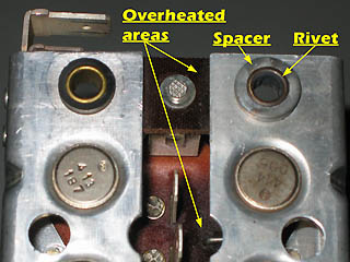
This
photo shows the cad-plated steel spacer and the brass rivet which are
part of the ground current path in the stock part. In time, a high
resistance develops between the heatsink and the rivet.You can see the
darkening of areas of the phenolic support and the circuit board
indicating overheating.
|
|
|
|
|
|
.
|
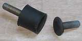
One of the broken upper rubber mounts. The lower ones were intact.
|
|
|
|
|
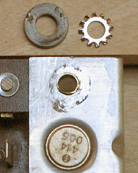
Here
the spacer has been released and removed and the excess rivet material
has been cut away and filed flush with the aluminum. The star washer
will be added in the final assembly.
|
|
|
|
|
|
|
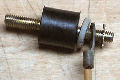
Here
is the assembly sequence. The spacer goes on the stud first and allows
the grounding lug to lay flat. The star washer goes between the lug and
the heatsink making a low-resistance connection between them.
|
