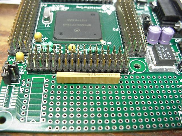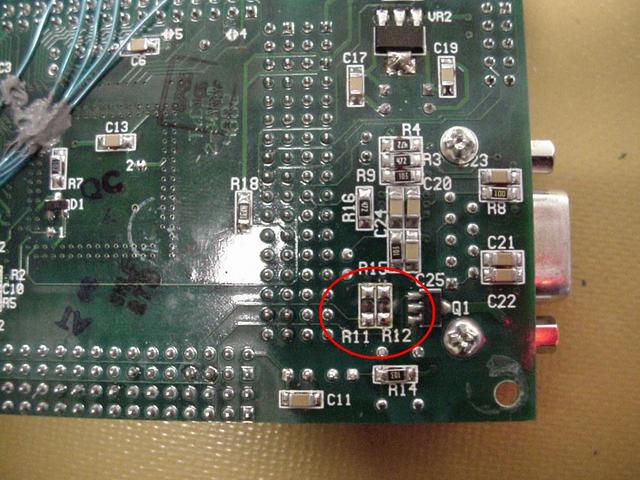
Need to do a few things to the Axiom PB-0555 PCB before we can install it into the ECM. One thing
that was needed to be added is pull-up resistors on some of the SPI CS lines. These were missed on the main PCB and
it is a lot easier to install them on the actual Axiom board. Being that the +5 volt supply is the same for the main
PCB and the Axiom we don't have to worry about supply turn on issues. A 10 pin bussed 10k SIP resistor package also gives
us a few extra pull-ups if needed. Block AA and Block
Z show these pull-up resistors.
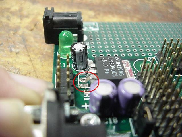
Also need to remove the straps to the MPC-555 ADC so that the ADC can be referenced to the precision
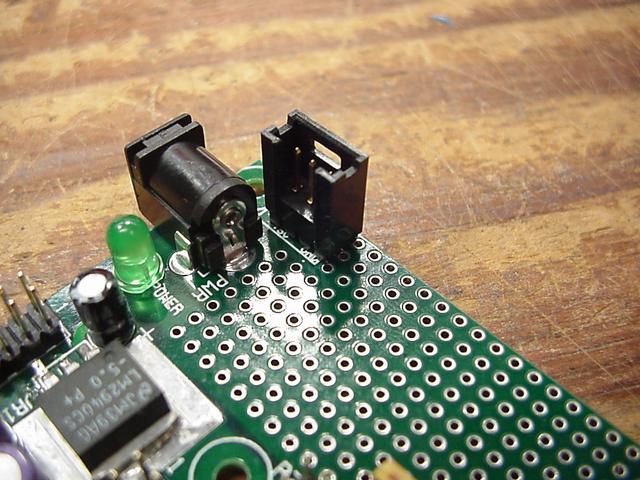
reference on the main PCB. An input power header needs to added also along with isolating the original +5 volt regulator
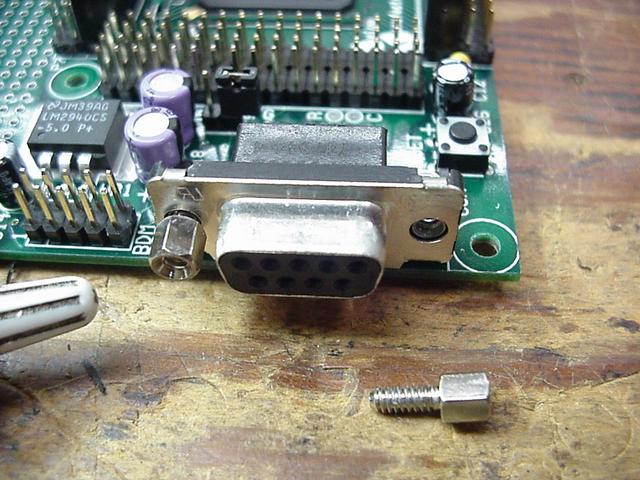
on the Axiom board. While looking at it I also noticed that the hex
bails on the RS-232 jack were never even tightened up. It certainly would be nice to have a hunk of metal floating inside the ECM. Finally
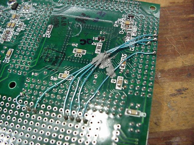
the MAX-232 serial interface IC needed to be isolated from the MPC-555 I/O lines. The main
PCB (Block O) has its own serial interface driving the outside world and that will be our main communication
path.
NOTE: The ADC Noise Fix page has a modified +5 volt reference configuration.