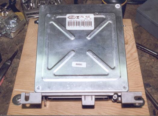
Well here is the brains of this operation.
An innocent looking little box that controls the whole show. If it
doesn't work right you go nowhere fast. Luckily with the current
level of technology today this hardware is very reliable, especially considering
the harsh environment it lives in. If you have every designed electronic
circuits for your ride you would know that the signal to noise ratio is
pretty poor. Trying to keep the harsh automotive environment out
while trying to process noisy input signals is no easy feat. The
ECU accomplishes this by some filtering in the hardware and some in the
firmware.
Well this unit is manufactured
by Margneti Marelli. The best I can figure is that this unit
was used on European cars (probably Italian - both Margneti Marelli and
Weber are Italian base companies). Some have suggested that this
is the same unit as used on 1992-93 Ford Escort RS Cosworth (model IAW48/P8).
They are similar but are not the same. The Ford unit has an extra
daughter board that mounts the EPROM while this unit the EPROM is socketed
on the main PCB. The model number of this pup is IAW4W6.
I would love to find out exactly what it came out of. Never can have
too many spares (I've got none so I feel naked). There is quite a
bit of unused hardware in this unit. It may be that this unit was
a general use ECU used in several different applications. You
can use this to your advantage. For example if you need to control
an electric radiator fan there are spare relay driver outputs that would
do the job nicely. There are also unused inputs that can be used
for some user specified purpose.
Most of the IC's, at least the ones
we are concerned with, are manufactured by SGS-Thompson. Getting
information for this company is pathetic. Using there WEB page is
an exercise in frustration, especially for component that are not being
manufactured today. Several key components took quite a bit of work
to figure out what they did. The easiest was the EF68B40PV
timer. This is functionally the same as Motorola's MC6840,
Hitachi's HD6340, or Thompson's EF6840. The large IC
marked
MA SOL1.0 turns out to be a PAL. Never could locate
what type/family this part is from. Most likely all the markings
on the device are house numbers of the programed part. I've figured
out the memory mapping function of this part, some of the latch addresses
but not all of them. There are several outputs that go to unused
sections of the hardware that I haven't had the need to figure out.
I would bet some could be easily identified as some bits of the latch at
$4000. Two bits I know (one is the fuel pump). It will take
a little more work to identify the address and latch bits for some of the
outputs. $6000 is another PAL latch that mostly reads the status
of the L9112D driver. The last really mystery part is another SGS-Thompson
jewel marked L9112D. At first I though this part was a MUX
of some kind but that proved wrong. It looks to be some esoteric
type of driver. It can be modeled as a inverting op-amp with a 4.7k
pull down on the input with a 75 ohm output impedance. Looking at
what it drives it is a mystery why they chose to uses a part like this.
Only two (2) sections of this hex part are used. One to drive the
injector pair (INJ-D) and the other is the ECU serial receiver input.
Most of the other key parts I was able to reason out what their functions
where.
The schematics I have created
are functional models. Most of the values for the capacitors are
unknown. Most have no direct affect on hardware performance as far
as we are concerned. Most serve as by-pass caps and high frequency
filtering. Most all of the resistors I could identify by value.
A few I had to measure. There are two modules, HY1 and HY2, that
filter the sensor inputs that are not entirely modeled. The DC transfer
function is modeled but their AC characteristics have not. I have
looked a little at their AC characteristics and what my casual impression
is that they are high frequency filtering, maybe even active filtering.
I do believe that I know enough about them and their transfer functions
that what is documented in the code is correct. The values that I've
pulled out of the ECU have correlated correctly to the input signals applied.
12/21/1999 -
While the ECM was out of the car while I was working
on the crank trigger stuff I did look a little closer at the MAP and TPS
circuits in the HY1 module. The MAP side is nothing significant but
the TPS side is fairly heavily filter. Schematics have been update.
| Pin | ECM #IAW4W6 | With Crank Trigger | ECM #IAW48/P8 |
|---|---|---|---|
| 1 | Ground | Ground | Ground |
| 2 | O2 Sensor | O2 Sensor | O2 Sensor |
| 3 | N/C - (Gnd) | Crank Trigger- (Gnd) | CrankRef- (Gnd) |
| 4 | N/C - (magnetic input) | CAM Position+ | CrankRef+ |
| 5 | Dist Return (Gnd) | CAM Position- (Gnd) | PhaseRef- (Gnd) |
| 6 | N/C - (Gnd) | N/C - (Gnd) | KnockSens- (Gnd) |
| 7 | N/C - (CA3262E-8) | N/C - (CA3262E-8) | Charcoal Canister |
| 8 | ECU Serial RX | ECU Serial RX | Diagnostic |
| 9 | N/C - AN1 Input | N/C - AN1 Input | - |
| 10 | Diode Protection | Diode Protection | Main Relay Contr. |
| 11 | Sense Return (Gnd) | Sense Return (Gnd) | Analog Return (Gnd) |
| 12 | N/C - (CA3262E-3) | N/C - (CA3262E-3) | Diagnostic Lamp |
| 13 | N/C - (PAL-2 input) | N/C - (PAL-2 input) | Service Connector |
| 14 | N/C - (PAL-1 input) | N/C - (PAL-1 input) | Service Connector |
| 15 | MAP Sensor+ | MAP Sensor+ | MAP Sensor+ |
| 16 | N/C - (Current Driver) | N/C - (Current Driver) | Waste Gate Solenoid |
| 17 | TPS Sensor+ | TPS Sensor+ | TPS Sensor+ |
| 18 | INJ-B (6&5) | INJ-B (6&5) | Injector 4 |
| 19 | Ground | Ground | Ground |
| 20 | ECU Power (+12 Relay) | ECU Power (+12 Relay) | ECU Power (+12 Relay) |
| 21 | N/C - (A/C sense) | N/C - (A/C sense) | A/C sense |
| 22 | N/C - (HY2 / AN0) | N/C - (HY2 / AN0) | KnockSens+ |
| 23 | Dist Trigger+ | Crank Trigger+ | PhaseRef+ |
| 24 | Ignition Return (SA-) | Ignition Return (SA-) | IgnOut- |
| 25 | Ignition Output (SA+) | Ignition Output (SA+) | IgnOut+ |
| 26 | N/C - Ignition Output | N/C - Ignition Output | - |
| 27 | ECU Serial TX | ECU Serial TX | Diagnostic |
| 28 | Fuel Pump Relay | Fuel Pump Relay | Fuel Pump Relay |
| 29 | Water Temp Sensor | Water Temp Sensor | Water Temp Signal |
| 30 | +5 volt Reference | +5 volt Reference | Analog Drive |
| 31 | MAT Sensor+ | MAT Sensor+ | IATsignal |
| 32 | INJ-D (2&7) | INJ-D (2&7) | Injector 2 |
| 33 | INJ-C (4&3) | INJ-C (4&3) | Injector 3 |
| 34 | IAC Motor | IAC Motor | Idle Valve Signal |
| 35 | INJ-A (1&8) | INJ-A (1&8) | Injector 1 |
Note: The connector definitions for the Crosworth ECM were found here: EFI reverse-engineering central