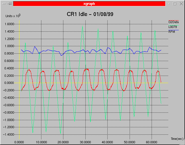
Not having closed loop idle isn't something that was broken in the code. I am not sure why they did not include closed loop idle capability. Being this unit was designed as a kind of a general EFI system and not to a specific motor / cam combination, maybe closed loop idle caused some kind of problem in a particular application. My cam is at the top of the wild list and you would think as you went milder any problems would become less sever. Don't know... One of the main reasons I wanted to close the loop at idle was the code's poor performance when the air temperature gets hot. I would have to set the Idle Fuel Modifier so rich so that when everything got good and heat soaked the idle mixture wouldn't lean out so much it would start surging severely. There is so much ignition advance at idle (in the high 40's) that I don't need such a rich mixture to keep the motor running reliably. I was always able to manually bring the idle mixture down and still maintain a decent idle.
Well we have all of the hardware in place to close the loop at idle. The heated O2 sensor being a big one. If the O2 sensor was not heated and your installation mounted it too far down stream there might have not been enough heat in the exhaust gases to keep the sensor up to its operating temperature. With the heated sensor this is not as large of a concern. My first attempt at closed loop idle was just to bring down the minimum closed loop RPM limit parameter. Well this did allow closed loop idle but I experienced quite a bit of off idle stumbling. The large cam needs extra fuel in this area because of its poor low RPM efficiency and dilution of the intake charge. I didn't really think this was going to work but it was simple so I gave it a shot.
These are the Closed Loop Idle Rules I have applied....
Below are some plots showing the progress from first attempts to what is happening today. You probably should check here for how these graphs are Scaled.

Well this was the first pass at closed loop idle. Basically all that was done at this point was to extend the minimum closed loop RPM rule to around 700 RPM. All the original closed loop algorithms are still in place at this point in time. You can see that the loop is way slow with the O2 sensor's response always lagging the fuel modifier (at $0079). Remember that a count of 16000 (1600 on the plot) is about a 20% change in fuel so there is almost a 40% peak-to-peak change in fuel going on here.
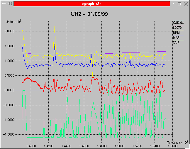
Here is where I started to break out the closed loop idle routines from the normal closed loop operations. You can see how the code was learning how much fuel was needed at idle. When the throttle was first closed the fuel modifier (L0079) went to the lean rail trying to bring in the O2 voltage. What you don't see on the plot is the main Idle Fuel Modifier at $00AB being adjust to bring the closed loop fuel modifier (L0079) off of the rail. As time progresses the Idle Fuel Modifier is pulled enough to keep the closed loop fuel modifier off of the rail.
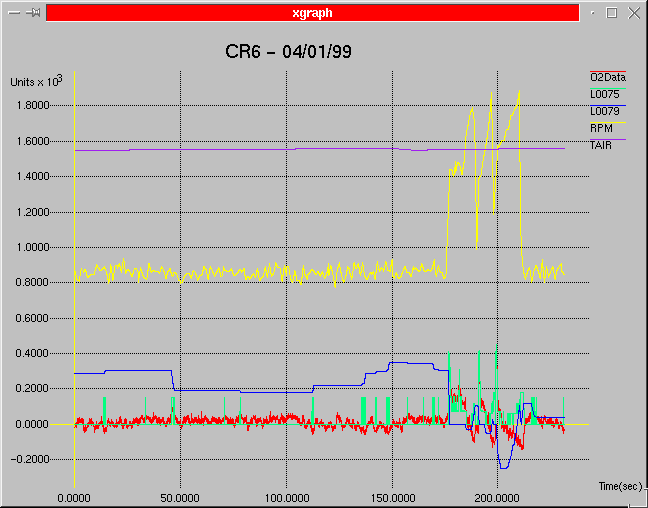
Here you can see the effects on closed loop idling of me trying to reduce the swing of the closed loop fuel modifier in L0079 during normal closed loop operations. The value at L0075 is the rate of change that the L0079 fuel modifier is adjusted every ignition event. What I was trying to do at this point in time was to slow the closed loop response some by reducing the rate of change as a function of O2 voltage (more on that in the O2 stabilization discussion). You can see that the value of L0075 was zero most of the time here leaving the fuel modifier at L0079 alone. You can see how little change in error voltage there is when you are not over controlling the fuel going into the motor. This worked well for idling but was not aggressive enough for higher RPM's.
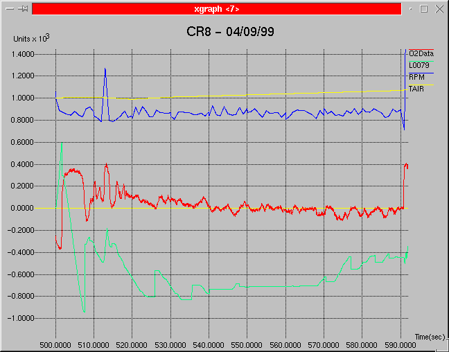
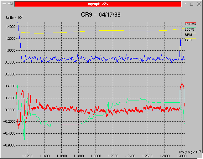
These two plots show the current state of the closed loop operations. If you look closely you see how the fuel modifier at L0079 steps back half way to the last toggle point and waits every time the O2 voltage crosses 447 mv. This is the technique that I am using to try to tame the normal closed loop operations. You can also see how much more stable the closed loop fuel modifier in L0079 is compared to the first plot above.