Temperature distribution in inner shell of double walled chamber subjected to radiation heat transfer |
Craig Boyak, PE Engineering Services providing ANSYS, Pressure Vessels,
Furnaces |
|
| |||
|
Engineering
Pressure Vessels |
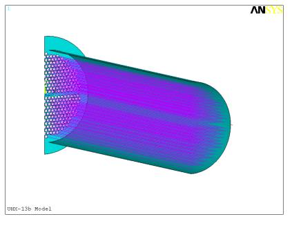
HX tube sheets, UHX Sometime in 2002 I became interested in the ASME's tubesheet criteria and methodology. At that time it was contained in Appendix AA in Sect VIII, Div 1. Now it is found in part UHX which is mandatory. I reviewed the background literature and mathematics and wrote an Excel spreadsheet to address fixed tube sheet designs to understand the various interactions between geometry, loads and materials. Next I found myself addressing the question of where, exactly, the limit of tube pattern uniformity ended so one could know if the ASME approach should be used for all those cases where impingement plates and baffles produced regions without tubes. I'm not sure I got to the answer of that question but during the course of studying the issue I created a parametric FEA model that allowed for inclusion (or not) of discrete tubes. The picture below shows a model replicating example problem UHX 20.2. Note that individual tube elements are included.
The model still required numerous idealizations and approximations to prevent it from becoming unmanageably large. The interpretation of results also required an understanding of how stresses were determined for the ASME approach. The following chart shows the comparison of tube sheet bending stresses as a function of radial position for the first 3 load cases for a tube expansion factor of 1.0
Also available from the model are tube axial stresses for all tubes not just the outer periphery. The following chart shows how the tube stresses vary as a function of radial position. Note the results match the UHX results at the periphery and suggest a completely different response at the center.
|
|
contact email address - CBoyakPE@sonic.net "An engineer is someone that can do for a nickel what any damn fool can do for a dollar."
|